Voltage unbalance (also called voltage imbalance) refers to the condition in a three-phase system when the voltages across the phases are not equal in magnitude or are displaced from the 120° phase difference. It can severely impact the performance of motors and electrical equipment.
This article explains how to calculate voltage unbalance using NEMA and IEC standards, what causes it, and its effects on motors and electrical equipment.
Voltage Unbalance – NEMA Definition
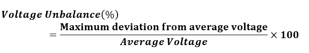
The voltage unbalance is defined as the maximum deviation from the average of three-phase voltage or current, divided by the average of the three-phase voltage or current. It is expressed in percent.
Voltage Unbalance Formula (NEMA)
This formula helps quantify voltage imbalance in electrical systems and identify potential risks to equipment.
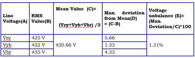
Voltage Imbalance Calculation Example
According to NEMA (National Electrical Manufacturers Association of USA), the standard equation is as given below.
Voltage unbalance
= Maximum deviation from mean of {Vry, Vyb, Vbc} / Mean of {Vry, Vyb, Vbc}
Given phase voltages:
- V1=400V
- V2=395V
- V3=390V
Step 1: Calculate the average voltage
Average Voltage=(400+395+390)/3=395 V
Step 2: Find the maximum deviation from the average
Max Deviation=∣400−395∣=5 V
Step 3: Use the NEMA formula for Voltage Imbalance
Voltage Unbalance (%) = (Max Deviation / Average Voltage) × 100
= (5 / 395) × 100
= 1.27%
Voltage Unbalance – IEC Definition
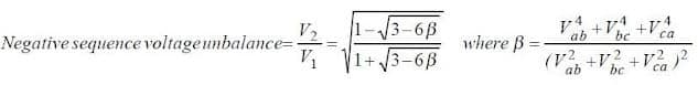
According to the IEC standard, the Voltage Unbalance Factor (VUF) is calculated by dividing the negative sequence voltage (V₂) by the positive sequence voltage (V₁) and multiplying by 100. This formula helps engineers accurately assess unbalance in three-phase systems.
It is expressed using the formula:
VUF = (V₂ / V₁) × 100
The unbalanced electrical network can be resolved into three balanced systems a positive sequence, negative sequence, and zero sequence system.
If the system is balanced, the negative sequence and zero sequence components would be absent.
Positive Sequence Components
A positive sequence means the magnitude of all three phases is equal, and phase displacement between the phases is 120 degrees. The impedance of each phase is identical.
As the applied voltage and the impedance of each phase are equal, the current in each phase would be identical.

In a positive sequence, all the electrical quantities are equal and displace each other by 120 degrees. The phasor diagram of positive phase sequence components is given below.
Negative Sequence Components
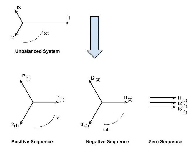
If the system voltage or impedance is imbalance , the negative phase sequence will flow in the circuit. The negative phase sequence current is of the same frequency; however, the sequence of the current is opposite to the sequence of positive sequence components.
If the positive sequence, negative sequence, and zero sequence components are designated as V1, V2, and V3, The negative unbalance factor (Voltage unbalance factor) = V2/ V1
If V₁ is positive and V₂ is negative sequence component:
Voltage Unbalance Factor (VUF) = (V2 / V1) × 100
How to Calculate Voltage Unbalance (Summary)
Voltage imbalance can be calculated using:
- NEMA formula: based on % deviation from average
- IEC method: based on sequence components
Both methods are crucial for system diagnostics and phase unbalance calculation.
Current Unbalance and Its Formula
The method of determining current imbalance is quite similar to the voltage imbalance formula, where deviation from average is the basis for calculation.
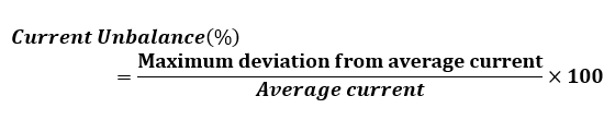
This is a common cause of overheating in motors.
Causes of Voltage Unbalance in 3-Phase Systems
Voltage unbalance usually happens due to uneven loading or inconsistencies in the electrical distribution system. Even if the system is designed to be balanced, several real-world factors can disturb it:
- Uneven single-phase load distribution: When single-phase loads are not evenly connected across the three phases, some phases carry more current, causing voltage drops.
- Unbalanced line or transformer impedance: Differences in cable lengths, sizes, or aging transformers can lead to unequal voltage drops.
- Loose or corroded connections: Poor terminal contacts increase resistance, resulting in localized voltage dips.
- Faulty or misadjusted voltage regulators and tap changers: If these devices are not properly set, they may fail to maintain equal voltages across all phases.
- Asymmetrical system faults: Ground faults or line-to-line faults can create lasting imbalance even after the fault is resolved.
- Utility-side or upstream issues: Sometimes the imbalance originates from the power source itself due to problems in generation or distribution.
Even small voltage unbalances (as low as 1–2%) can cause large current unbalances, leading to overheating, derating, or early failure of motors and other sensitive equipment.
Voltage Unbalance Mitigation in 3 Phase
Voltage unbalance is a common power quality issue, especially in distribution networks. While it’s nearly impossible to eliminate voltage imbalance completely, it can be significantly reduced with the right strategies.
Why Zero Voltage Unbalance Is Not Practically Achievable
There are three key reasons why total elimination of voltage unbalance is unrealistic:
- Random Connection of Single-Phase Loads
Consumers connect single-phase loads arbitrarily, leading to uneven phase loading. - Uneven Load Distribution
Real-world three-phase systems rarely achieve perfect load symmetry across all phases. - System Asymmetry
Physical asymmetries in transmission lines, transformers, and network topology inherently introduce imbalance.
Despite these challenges, voltage unbalance can be mitigated effectively through targeted analysis and corrective actions.
Practical Methods to Reduce Voltage Unbalance
To minimize voltage unbalance and its effects on motors and sensitive equipment, consider the following mitigation techniques:
1. Utility-Level Measures
- Implement phase balancing transformers or devices at substations.
- Monitor feeders in real time and switch loads dynamically where feasible.
2. Load Redistribution
- Evenly distribute single-phase loads across all three phases to balance current draw.
- Avoid connecting large single-phase loads to only one phase.
3. Minimize Impedance Imbalance
- Use identical lengths and sizes for phase conductors where possible.
- Maintain symmetrical transformer winding and consistent line construction.
4. Control of Voltage Regulators
- Reduce overuse of single-phase voltage regulators; while they can help balance voltage, improper use may worsen the condition on other phases.
5. Use of Power Electronics
- Employ active power filters and static VAR compensators (SVCs) for dynamic correction.
- Passive filters or phase balancing devices can be used where active solutions are not feasible.
Conclusion
Voltage unbalance affects the performance and lifespan of electrical systems. It can be calculated using:
- NEMA formula – based on deviation from average voltage
- Voltage unbalance factor formula (VUF) – based on sequence components (IEC)
Understanding both helps prevent equipment damage, reduce energy losses, and ensure system reliability. Regular checks are essential for safe and efficient operation.
FAQs – Voltage Unbalance
According to NEMA guidelines, an acceptable voltage imbalance is less than 1%. If the unbalance exceeds this threshold, it can lead to overheating and reduced efficiency of motors and equipment.
To measure voltage imbalance, record the voltages between all three phase pairs (Vab, Vbc, and Vca). Then, calculate the average voltage and the maximum deviation from this average. Use the voltage imbalance formula:
Voltage Imbalance (%) = (Max Deviation / Average Voltage) × 100
Voltage imbalance in motors is often caused by:
Unequal distribution of single-phase loads
Loose connections
Faulty wiring or transformer issues
Uneven impedance across phases
These imbalances can lead to excessive heat, vibration, and premature motor failure.
Voltage unbalance refers to the difference in voltage magnitudes across a three-phase system, while current unbalance occurs when the phase currents are not equal.
Even a small voltage imbalance (e.g., 2%) can result in a significantly higher current imbalance (6–10%), which impacts motor performance more severely.
Related Articles: