In this article, we will discuss the PID controller and its working. PID controllers are used for controlling the process in a closed loop for precise controls. A well-tuned PID controller increases the production and product quality.
PID is abbreviation for Proportional(P), Integral(I) and Derivative(D). We can form the different types of controllers using proportional control, integral control, and derivation control by combining features of the individual controllers.
Basically, Proportional, Integral, and Derivative are a kind of different controllers having their own unique properties. But due to some or the other limitations, Proportional, Integral, and Derivative are not used alone. Although all three of them can be used individually the combination of them is used to get the best response from the system. we use them in combination, such as PI, PD & PID.
PID controller is used in a closed loop system to get the desired output for a given input to the system. PID controller generates output such that the error is almost zero. The system response is also very stable provided that the tuning of the PID controller is good.
First of all, let us divide the PID controller into three parts. The three parts are the Proportional Controller, the Integral Controller, and the Derivative Controller.
Proportional Controller
A proportional controller or commonly called a P controller gives the output which is proportional to the input to the controller. A multiplication factor is multiplied by the input given to the Proportional controller. The multiplication factor is called the Proportional Gain Factor (KP)of the proportional controller.
The more the value of the proportional gain factor, the faster is the response of the control system. On the other hand, the lesser value of the proportional gain factor leads slower response of the control system.
The control system must be as fast as possible to have tighter process control. But the only problem we face by increasing the proportional gain factor (KP) is that the overshoots and undershoots in the system increase. Also, by decreasing the proportional gain factor (KP), the output of the control system becomes slow which is not acceptable for many systems.
Mathematically, a Proportional controller is defined by:
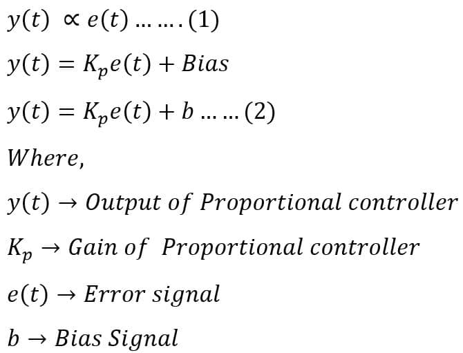
Here, the Bias signal is a constant term that we add to the output of the proportional controller.
The reason for using Bias is very simple. As discussed, the output of the proportional controller is proportional to the input of the proportional controller. Assume that we need to control the level of a tank by controlling a control valve by a proportional controller. The proportional controller issues a command to the control valve as per the error signal. The error signal is the difference between the set point value and the actual value.
Suppose the tank level set point is 70%. The control valve gets a command from the controller and closes to till the tank achieves a 70 % level. The error is zero when the actual level of the tank is equal to the set point. Therefore, in this condition, the output of the proportional controller becomes zero.
Now, if again the tank level increases or decreases then the proportional controller will not give a command to the control valve to maintain the level. To mitigate this problem we use a bias. So, when the input of the proportional controller goes to 0, at that time this Bias will be giving some command to the proportional controller.
The proportional controller functions as an On-Off controller when the value of proportional gain factor (KP) value is very high.
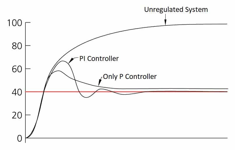
One more disadvantage of the Proportional Controller is that this controller produces a steady-state error. The offset is a special term used for this. In other words, we can say that the proportional controller causes a constant error between the input and output signal. The Proportional Controller cannot eliminate this error.
Integral Controller
The proportional controller takes into consideration the value of the error at the time of output calculation. This produces a steady-state error or says offset in the system. The Integral Controller takes into consideration the history of the error or says the time duration for which the error has persisted.
The integral controller keeps adjusting (i.e. increasing or decreasing the output depending on the type of system.) till the sum of errors becomes 0.
Mathematically, an Integral controller is defined by:
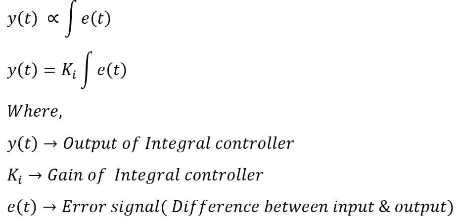
For an integral controller, very small error values can also lead to a large amount of outputs as an integration of the error for the whole time is being used. The integral controller produces output and adds to the output of the proportional controller’s output over a period of time to eliminate the steady-state error.
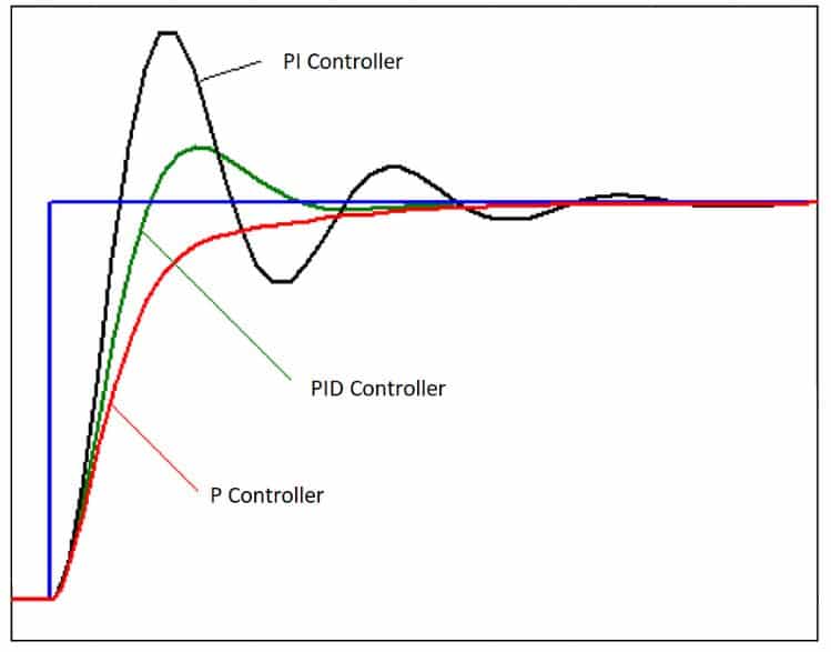
Combining the Proportional and Integral controllers gives a good output. The system also becomes stable up to an extent.
Derivative Controller
Both the above controllers discussed work only seeing the present and the past. The Derivative controller predicts the future behavior of the error. The output of the derivative controller changes with respect to the rate of the change of the error with respect to the time. A derivative controller is only used when the processor variable starts oscillating or starts changing at a very high rate of speed.
The derivative controller helps in improving the system’s response and thereby decreasing the settling time of the system’s response. The derivative gain is directly proportional to the speed of the system. This means that the increase in the derivative gain of the derivative controller will increase the response time of the system.
Mathematically, the Derivative controller is defined by:
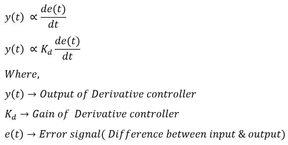
A derivative controller cannot be used alone. This type of controller is generally used with a Proportional controller and an Integral controller as a PID controller or a Proportional controller as a PD controller. The derivative controller is used to decrease the lag in the control system’s output.
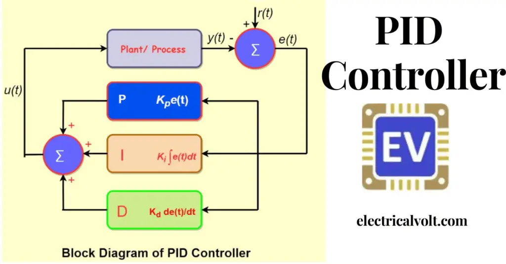
What is PID controller?
PID controller makes use of Proportional, Integral, and Derivative controllers. All three controllers’ response is merged to get an output which eliminates the disadvantages of the individual single controller.
The principle of operation behind the PID controller is that the proportional, integral, and derivative terms need to be individually adjusted or “tuned”.
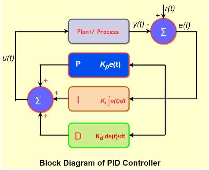
Based on the difference between these values, the correction factor is calculated and applied to the input. The three steps are:
- Proportional adjustment includes the correction of settings proportional to the difference between the set point and the output. Therefore, when the difference approaches zero, the target value is never reached and the correction is applied.
- Integral Tuning attempts to correct this by effectively accumulating error results from the “P” action and increasing the correction factor. However, an “I” will try to eliminate cumulative error instead of stopping output when the target is reached, resulting in an overshoot.
- Derivative Tuning attempts to minimize this overshoot by slowing down the correction factor applied as it approaches the target.
The purpose of the PID controller is to force feedback that matches the set point given to the system. PID controllers are the best controllers used in systems that have a relatively small mass and respond quickly to changes in energy input to the process.
PID controllers are mainly recommended for systems where the load changes are observed frequently and the controller needs to automatically compensate for frequent changes in set point.
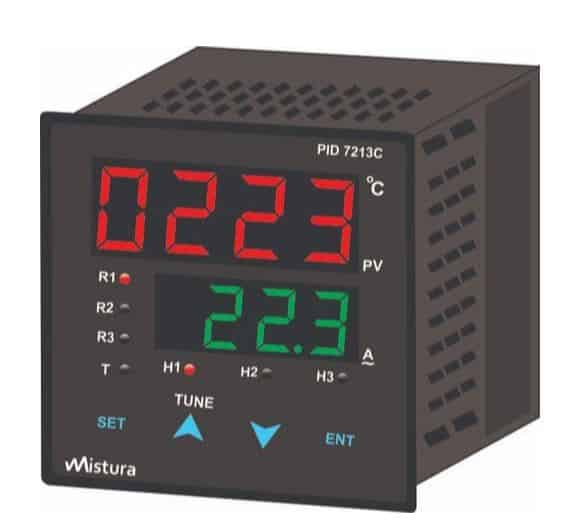
There are various types of PID controllers. Some PID controllers are separate physical units like a kind of stand-alone system. While other PID controllers are available in the systems like PLC or DCS. The PID controllers which are available in markets have various functions which can be configured using the buttons given on the controller.
Various functions can be set and also the values of the PID can be easily set. Some PID controllers even have relays for use in critical systems. Generally, temperature control is done using these external PID controllers.
The input from the primary sensor is directly wired to the PID controller. Upon receiving input from the primary sensor and a set point in the controller, the PID controller generates an output. This output can directly be used to control any final control element.
For PID controllers in the system like PLC or DCS, inbuilt function blocks are available. The only access to the program for that PID block is necessary.