In this article, we will discuss the Response Time test of RTD and thermocouple. RTD and Thermocouple are the primary sensing elements for temperature measurement. Temperature measurement is one of the most important parameters which is to be measured continuously.
Why is Response Time Test required?
The response time test is required for all temperature sensing elements installed in all plants. This response time test is done to ensure that the response of the RTD or thermocouple is within the acceptable limits and ok to use. The response time test for RTD and thermocouple is done to ensure that
- The sensor i.e. RTD and thermocouple are responding properly within a specified period as per process requirement. RTD and thermocouples’ response time generally decreases with the aging effect.
- To ensure that the air gap or dirt or flying Bagasse particles inside the thermowell don’t change the response time of the RTD and thermocouple.
- To know the problem between Sensor and Cable Connectivity.
- To diagnose the sensor and process irregularity.
What are different methods for Response Time Test?
Response time of the temperature elements like RTD and thermocouple can be tested by using the below-mentioned two methods.
- Self-Heating Index (SHI)
- Loop Current Step Response (LCSR)
The response time of the temperature sensing element is defined by one term called Plunge Time (T). This is the single parameter that can give us an idea about the response time of the temperature sensing element.
What is Plunge Time?
Plunge time is the time taken by any temperature sensing element to produce an output of 65% to 66% of the actual value in the process.
Method 1: Self-Heating Index (SHI)
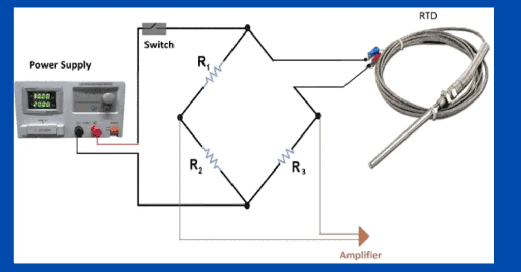
The method of a self-heating index is used to test the response time of the RTD. Self-heating index is the ratio of change in the resistance to that of the electric power generated in the RTD’s sensing element. This test applies only to RTDs. This test is performed to detect the gross change in the Response Time of RTDs. The self-heating index makes use of the Wheatstone bridge circuit. The unit of it is ohm/watt
We can use the below-mentioned procedure for the self-heating test of RTD.
- The Wheatstone Bridge which is used should be balanced
- Measure the resistance of RTD using an accurate multimeter, the current measured should be within 2 mA
- Now switch the current to high value. The High current’s value must be 5 mA.
- Let the RTD reach a steady state. It will take a few seconds.
- Now set the Wheatstone bridge to balance condition as per the new value of the RTD.
- Record the RTD’s output value in a data chart. The noted value can be in the form of Resistance i.e. Ohm or Current i.e. mA or Power i.e. milli Watt
- Raise the current to its range value and note down the values. Repeat it 5 times.
- Plot the “Self-Heating Curve” graph data in terms of RTD Resistance (R) versus Power (P).
- Calculate the slope of the line. The path for self-heating data we captured should be a straight line path. If not then repeat the procedure.
- Calculate the slope. The value of the slope we observed is the Self-Heating Index.
Loop Current Step Response (LCSR)
LCSR method is used to measure the response time of RTD and thermocouple remotely when the sensor is installed in the running process field. In this test, and we apply electric current at the end of temperature sensor extension leads. The applied electric current causes the temperature sensor to heat and this result in the change in temperature transient inside the temperature sensor.
Now the electric current is reduced which results in cooling. The time plot of this temperature sensor heating and cooling is recorded during the LCSR test. The LCSR transformation represents the temperature sensor response time.
The LCSR test takes into consideration all the effects of installation and process conditions. This test provides a sensor’s actual Response time. The Loop Current Step Response (LCSR) Test Procedure is different for RTD and Thermocouple.
RTD Loop Current Step Response(LCSR) Test Procedure
The Loop Current Step Response Test Procedure for RTD:
- We use a Wheatstone bridge to perform the LCSR test for RTD.
- The Wheatstone bridge must be balanced with RTD with a current of 1 mA to 2 mA.
- Now switch the current to high value. The value can be in the range of 30mA to 50 mA.
- Now, wait till the RTD stabilizes for the new current applied. It will take a few seconds.
- The rise in RTD’s temperature will depend on the magnitude of the heating current applied and the surrounding environment.
- Generally, during the LCSR test, the RTD gets heated to about 5 oC to 15 oC.
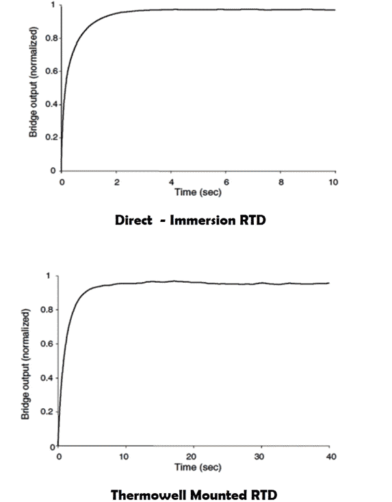
The above figure shows the graph of 2 LCSR test transients. One of Direct-Immersion RTD and the other of Thermowell-Mounted RTD. Both these transients are from the LCSR testing of the RTDs in power plants using a heating current source of about 40 mA. It is evident that the direct immersed RTD has a better and faster Response Time than the thermowell mounted RTD.
The transients are caused by internal heating and cannot provide us with the RTD’s response time until the data is transformed. To provide the necessary current for the LCSR test, the power supply present in the Wheatstone bridge must be adjusted so that the high current must lie between 30 mA and 50 mA, depending on the RTD and the process in which it is installed.
If the RTD is installed in a stable process, then only 30 mA is enough. On the other hand, if the RTD is installed in a process that has large temperature fluctuations, a higher current of 50 mA is required to improve output.
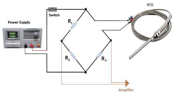
To adjust the amplitude, we get for the LCSR signal an amplifier is used at the output of the Wheatstone bridge as shown in the figure. An important thing to note is that the Wheatstone bridge’s output voltage changes almost linearly with the changes in the RTD resistance during the LCSR test.
Thermocouple Loop Current Step Response Test Procedure
The LCSR test procedure for Thermocouple and RTD is very different even though the principle of the test and the analysis is the same for both RTD and Thermocouple.
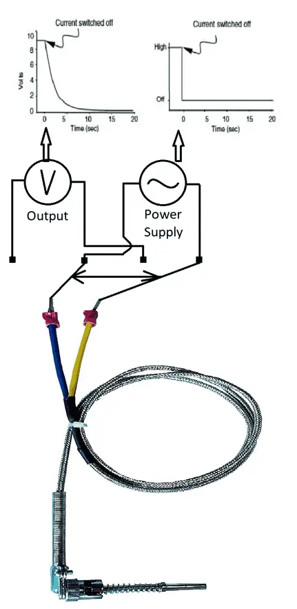
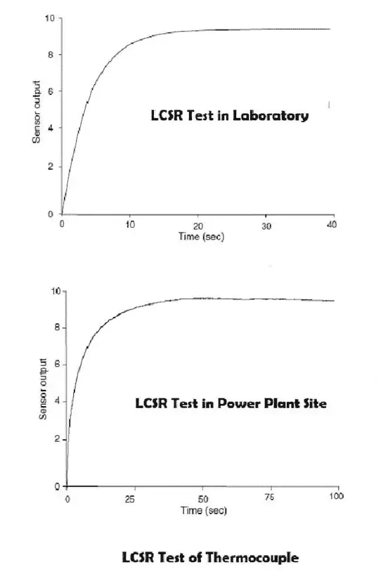
For LCSR testing of the thermocouples, we need an AC current signal. The reason for this is that the AC signal cancels out the Peltier effect at the thermocouple junction. A higher current of 500 mA is required because the thermocouple circuit resistance is distributed along the length of the thermocouple. The whole Thermocouple sensor is heated by applying the LCSR test current.
Difference between the LCSR testing of RTD and Thermocouple:
In LCSR testing of RTDs, the RTD is heating up and the data is being collected as current is running through the circuit.
In LCSR testing of Thermocouples, the data is only collected after the current is switched off and while the thermocouple is cooling to ambient temperature.
Key Points:
- Self-heating test can only be done on RTD
- Plunge Test and LCSR test can be done for RTD as well as thermocouple
- Plunge test is only done in laboratories. While in the LCSR test, special test equipment is needed and analysis is complex.