Jean Charles Peltier a French physicist 1834 discovered the thermoelectric effect while doing his research on electricity. The Peltier effect consists of passing a current through a circuit made up of different materials. Its junctions are at the same temperature, producing the reverse effect of the Seebeck (thermoelectric effect).
In this case, one junction absorbs the heat, and the other junction liberates the heat on the other side. The part that gets cold is usually around 10° C approximately. At the same time, the part that absorbs heat can quickly reach 80° C.
One interesting fact is that, by reversing the power supply polarity, it is possible to reverse the process. As a result, the surface which previously generated cold begins to generate heat. Also, the surfaces that generated heat begin to generate cold.
Until now, this interesting phenomenon has been reduced to a few small applications.
Seebeck Effect

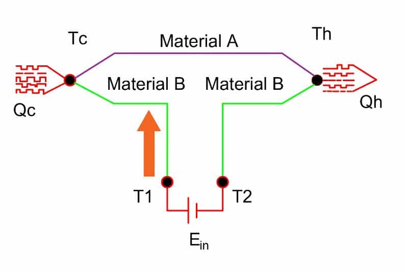
The Seebeck effect is the conversion of heat directly into electric potential at the junction of two dissimilar metals of conduction. It was named after German physicist Thomas Johann Seebeck.
As shown in the above figure, there are two conductors A and B of different metals. We treat the temperature at junction A as a reference temperature. The reference junction is maintained at a relatively cool temperature Tc. The junction temperature at B is higher than temperature Tc. Upon heating junction B, a potential difference ( Eout) develops between the terminal points T1 and T2. Therefore, the difference in temperatures causes an electric current to flow continuously in this closed circuit. The potential developed across the junction is known as Seebeck EMF.
We can express it as;
Eout = α (Th – Tc)
Peltier’s Effect
The Peltier effect is the opposite of the thermoelectric phenomenon of the Seebeck effect. In this case, when electric current flow within the closed-circuit, one junction of two dissimilar metals absorbs thermal energy in one junction and discharge the same energy at another junction.
On application of a voltage between the terminals T1 and T2, an electrical current (I) flows in the circuit. As a result of current flows, a slight cooling effect takes place at junction Qc and a slight heating effect occurs at junction Qh. The reverse process happens by changing the direction of the current flow.
If QC is the rate of cooling in watts, and Qh is the rate of heating in watts, I is the current flowing through the closed circuit.
The rate of cooling is
QC = β x I
Where, β is the differential Peltier coefficient between the two materials A and B in volts.
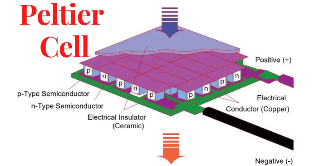
Peltier Effect and Peltier Cells
It is possible to comprehend the Peltier effect through the Peltier cells. When the Peltier cell receives the electrical power, the temperature difference establishes between the two faces of the cell. This temperature difference depends on the ambient temperature where the PELTIER cell is located. Also, it depends on the body that we want to cool or heat.
Its use is rather for cooling since for heating there are electrical resistors, which are much more efficient in this task than Peltier cells. These are much more effective in cooling since their small size makes them ideal for replacing expensive and bulky gas- or water-assisted cooling equipment.
Application of Peltier cells
The practical applications of these cells are endless. The Peltier cells find their wide application in consumer electronics such as computers, compact refrigerators, and satellites. We use Peltier cells in spacecraft to overcome the effect of sunlight on one side of the craft by dissipating the heat over the cold shaded side, used in spectrometers.
The list could be endless since there are many applications in which it is necessary to use cold and heat at the same time. Peltier cell is practically made up of two semiconductor materials, one with an N channel and the other with a P channel. A cooper foil connects both N channel and P channel.
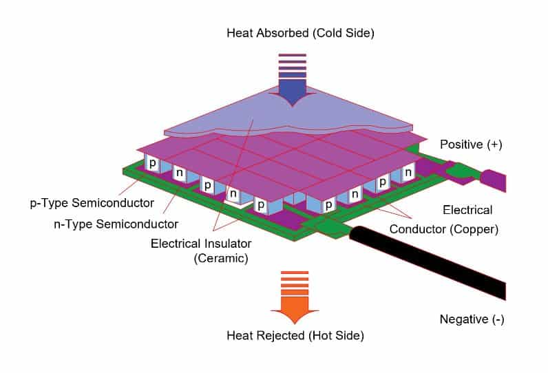
When the N material side receives positive supply and P material side receive negative supply, the upper copper plate cools, while the lower one heats.
If in this same cell, if we reverse the supply polarity, that is, the N material side receives negative supply and P material side receive positive supply. Then the upper part heats and the lower one cools.
Advantages of Peltier cells
Due to the immense advances in the field of semiconductors, today, they are built solidly and the size of a coin. Peltier cells are made of semiconductors like Tellurium and Bismuth to type P or N (good conductors of electricity and bad of heat). This facilitates the transfer of heat from the cold to the hot side by the effect of a direct current.
- As Peltier cells don’t have moving parts, the requirement of maintenance frequency is less.
- The Peltier cells won’t emit chlorofluorocarbons (CFCs)
- Temperature control can be maintained within fractions of a degree.
- Flexible form, in particular, can be very small in size.
- Can be used in smaller or harsher environments than conventional cooling.
- Long life, with a mean time between failures exceeding 100,000 hours.
- Controllable by variation of the input voltage/current
Disadvantages of Peltier cells
Peltier units also have some drawbacks to consider. Such as the
- High electrical consumption, or that depending on the temperature and humidity,
- Condensation may occur and, under certain conditions, even the possibility of formation of ice.
- There is limitation of heat dissipation.
- They are not suitable for high heat generation systems.
- Risks of burns.
- Risk of direct electrical contacts.
- The heat generated by the cell, if not dissipated may damage the cell.
Read Next:
The above given description about Peltier Effect, its uses and advantages/disadvantages was very useful to read and easy to understand. I hope the newsletter about automation and controls would be useful for me as student/practitioner of electrical technology.
Best wishes for your technical team in developing and continuously improving the technical articles for spreading technological knowledge around the globe. Engineer Zafar Iqbal Pakistan