In this article, we will discuss the ControlLogix Architecture of Rockwell Automation PLC. This PLC is famous for AB PLC(1756 ControlLogix).
ControlLogix Architecture
As we can see in the image, the ControlLogix 1756 PLC system consists of redundant power supply modules, Communication module, Controller (1756-L55xx), Redundancy module, and ControlNet Communication modules (1756-CNBR), Remote IO modules & some other modules like flex IO & AC drive module.
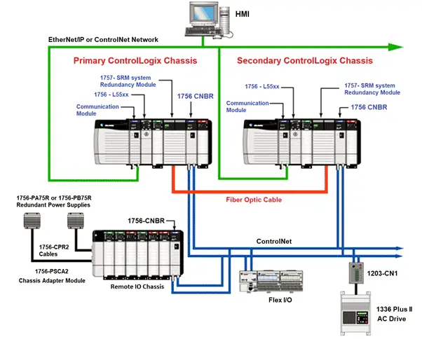
In ControlLogix 1756 PLC system, two redundant controllers are present. Both the controllers are present in two different chassis. Both the chassis have their own power supply. Because of this if any one power supply fails then the controller in that chassis also goes down. But another controller is working and our plant is running without any disruption. The controller sometimes called CPU is identified by a key slot. A key slot is present on the controller to change the mode of the controller.
Redundancy between these two controllers is to be established. For this purpose, Redundancy modules are installed in both chassis. Both the Redundancy modules are connected using a Fiber Optic cable. After the redundancy modules in both the redundant chassis are connected and powered ON, the Redundancy module determines which chassis is the primary chassis and which is the secondary chassis.
Here we can see two chassis with individual controllers/ So we can call them two PLC systems. One can be called PLC A and the other can be called PLC B. We can also call them Primary PLC and Secondary PLC. PLC A and PLC B are absolute locations. Once defined, the location cannot be changed. But Primary PLC controller and Secondary PLC controller can be on either chassis. Always one PLC controller which is primary executes the program and the other PLC controller is in sync mode.
When any fault occurs in the primary controller, the secondary controller becomes the primary controller. This is called the switchover of the controller. The switchover occurs as fast as 20 milliseconds.
The architecture shown in the image is having remote Input-Output chassis also. In remote Input-Output chassis, Input-Output cards are installed. Generally, this is used when we have Input-Output located at a distant place from the controller chassis. This remote Input-Output chassis has its own redundant power supply.
For establishing the connection between the controller and the remote Input-Output, communication such as ControlNet is used. ControlNet is used for internal communication between the controller and the Input-Output modules and other special types of cards if used. For using this ControlNet, we have to use a CNBR card of Allen Bradley.
We can also go with Ethernet communication instead of ControlNet communication. Ethernet is having very high bandwidth of 100 Mbps to 1 Gbps based on the module type. While ControlNet has an only limited bandwidth of 5 Mbps. This is the reason why Ethernet is mostly preferred. Other communication protocols like DeviceNet, Modbus, DH485, and SynchLink are also available in the market.
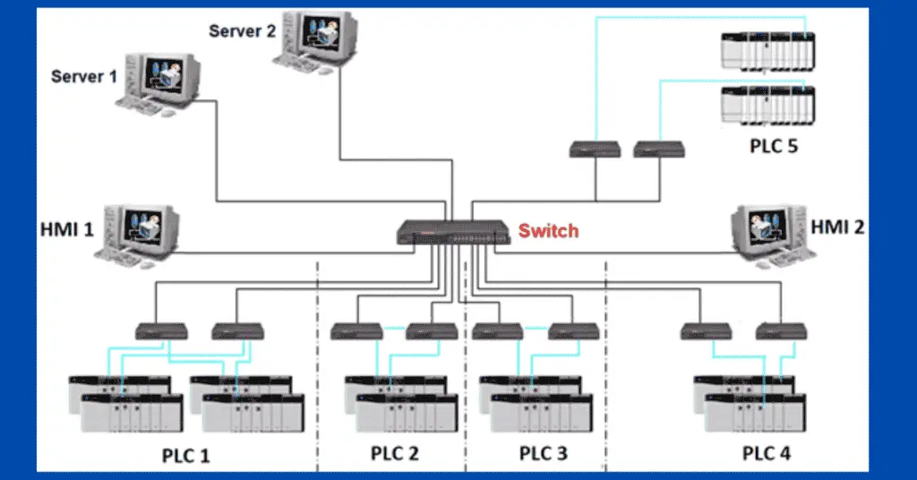
The architecture we have seen consists of only one PLC system and its own remote Input-Output chassis and other cards like Flex I/O, various drive controllers as well as HMIs. But in a big industry, there will be too many plants. For each plant, there will be a dedicated PLC. So, we also need to access PLC from different areas sometimes. For this, the PLC should be present in a network. An example of such a network is shown in the below image.
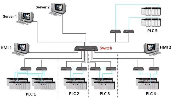
As seen there are various PLCs for different plants. These PLCs are connected to a switch which can also be a redundant switch. This connection forms a network. Also, servers and HMI are connected to this network through switch only. For making PLC connect to a network, each PLC should have an n unique IP address. The communication is usually through Ethernet communication protocol.
This is all about the architecture of AB PLC ControlLogix.