Transformer Over Fluxing Protection protects the core from overheating caused by over-fluxing. The voltage and frequency ratio (V/f) is responsible for over-fluxing in the transformer. In this post, we will learn about Transformer Over Fluxing Protection.
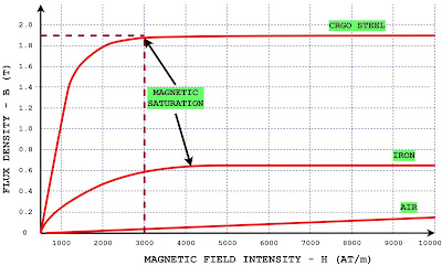
Flux density of the CRGO Core
The cold rolled grain oriented (CRGO) core is used in the transformer. The flux produced in the primary travels through the magnetic core and gets linked to the secondary.
The maximum flux density of the CRGO core is 1.9 Tesla, and if the core is magnetized above this rated capacity, the core gets saturated. The saturation of the core causes heating in the core and other parts of the transformer.
The flux density in the core should not increase above the rated value to avoid over-fluxing. Therefore, the designed flux density of the core is always kept below the maximum rated flux density of the core.
The over-fluxing relay is used to protect the transformer and measures the V/f ratio to calculate the flux.
The magnetization curve of the different materials is given below.
Transformer Over Fluxing Protection
The transformer is designed for the flux density of 1.7 Tesla so that a 110% increase in the flux density can be allowed.
The maximum over-fluxing in the transformer shall not exceed 110% of the designed flux density, and the transformer can be operated continuously at 110% of the designed flux density.
However, the transformer operation above 110% and up to 130% of the flux density can be allowed for a shorter time.
If the flux density increases to 140%, the transformer shall be tripped instantaneously to avoid permanent damage.
The flux density in the core is proportional to the ratio of V/f. The flux in the core remains constant for the constant V/f ratio. The mathematical expression of the flux density is given below.
Mathematical Expression of Flux Density
The voltage induced in the primary when the sinusoidal voltage is applied is
E=4.44 ΦfN
Φ=E/4.44f N
The Number of turns in the primary is constant for a given transformer
Φ=K* E/f
The induced voltage is approximately proportional to the applied voltage if the primary impedance is ignored.
Φ=K*V/f ———-(1)
The flux density in the core of the core is as given below.
B=Φ/A
Where A is the cross-section area of the core that is also constant.
B=K/A*V/f
B=K1*V/f ———–(2)
B ∝ V/f
Thus, the flux density in the core is directly proportional to the ratio of V/f if the number of turns of the primary is fixed.
Over fluxing Protection
The sudden increase in voltage due to power system transients may cause overfluxing. However, the transient overvoltage or overshoot dies down very fast.
Therefore, the instantaneous tripping of the transformer is undesirable.
The flux density is proportional to the ratio of voltage to frequency (V/f), and the ratio must be detected if its value is greater than unity.
The over fluxing function is generally incorporated in the microprocessor-based transformer protection relay in which all the transformer protections like differential protection, overcurrent, over voltage, under voltage, Restricted Earth fault protection, voltage unbalance, vector shift detection, over frequency, under frequency, and over fluxing protection can be programmed and enabled.
Microprocessor-Based Transformer Protection Relay
The transformer protection relay measures the input voltage and the supply frequency.
The block diagram of the over-fluxing, over/under voltage, and over/under frequency relays is given below.
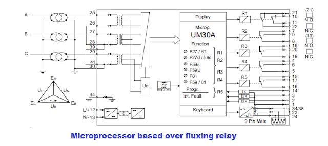
The relay measures the voltage and the frequency of the supply source. It calculates the ratio of the Volt/hertz on a real-time basis and compares the measured value with the setpoint.
Over Fluxing Protection Settings
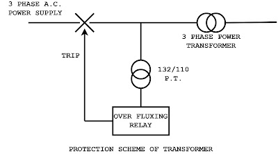
The relay is programmed for an inverse definite minimum time (IDMT characteristics). The setting of the over-fluxing can be done for 110 to 140 % of the rated flux of the transformer. The protection scheme of the transformer is given below.
Over Fluxing Protection for the Transformer Provided with a Tap-Changer
The flux in the transformer core is proportional to the V/f and inversely proportional to the number of turns in the primary.
The transformer without a tap-changer has a fixed number of turns in the primary, and the flux is directly proportional to the V/f ratio.
Let us take the case of the step-down transformer 132/6.6 KV. The 132 KV is stepped down to 110 volts and fed to the over-fluxing relay. The ratio of V/f is equal to 2.2 (110/50).
The over-fluxing relay is set at 110% of the nominal flux density, which is 2.42 (1.1 × 2.2). The relay will not trip if the V/f ratio is equal to 2.42.
If the V/f ratio increases from 2.2, the inverse definite minimum time (IDMT) characteristics will issue a trip command after a time lag as decided by the IDMT curve. If the V/f ratio is 3.08, the relay will trip the transformer breaker instantaneously.
Tap-Changer Operation and Over Flux Relay Detection
The tap changer is fitted at the high-voltage side of the transformer to increase or decrease the number of primary turns.
If the incoming supply voltage increases, the secondary voltage can be reduced by inserting the additional turns in the primary winding through the tap changer.
Thus, the flux in the transformer gets reduced. However, the relay will observe the over-fluxing condition because the voltage and frequency measuring points are taken from the primary supply.
In this condition, the relay will sense the over-fluxing, even though the flux in the core is well within the permissible range.
Preventing Unwanted Tripping During Tap-Changer Adjustment
In this situation, the over-fluxing relay has to be prevented from issuing the trip command to the circuit breaker. The secondary voltage increases proportionally with a decrease in the number of primary turns.
In this situation, the over-fluxing relay has to be prevented from issuing the trip command to the circuit breaker. The secondary voltage increases proportionally with a decrease in the number of primary turns.
The same can be observed on the secondary side of PT, and the tripping on over-flux protection can be prevented.
Conclusion
Transformer over-fluxing protection is vital to safeguard the magnetic core from overheating and saturation due to abnormal V/f ratios.
Since flux density is directly proportional to voltage and inversely proportional to frequency, any imbalance can lead to core damage.
Modern microprocessor-based relays accurately monitor the V/f ratio and initiate timely protection using IDMT characteristics.
In tap-changing transformers, special care is required to avoid nuisance tripping during voltage regulation. A well-set over-fluxing relay ensures reliable transformer operation under varying system conditions, preventing insulation damage and extending transformer life.
Related Articles:
very good