The superposition theorem is used to analyze electric circuits containing multiple sources. This article describes the statement and steps involved and solved examples of the superposition theorem.
Statement of Superposition Theorem
The superposition position theorem states that,
In a linear bilateral electric circuit containing more than one independent voltage and/or current source, the response (voltage or current) of a circuit element is equal to the algebraic sum of the responses (voltage or current) of that element by considering one source at a time with all other sources deactivated.
This statement can be understood as below:
Consider an electric circuit containing two independent voltage sources, V1 and V2 and we want to find the current through the resistor R3.
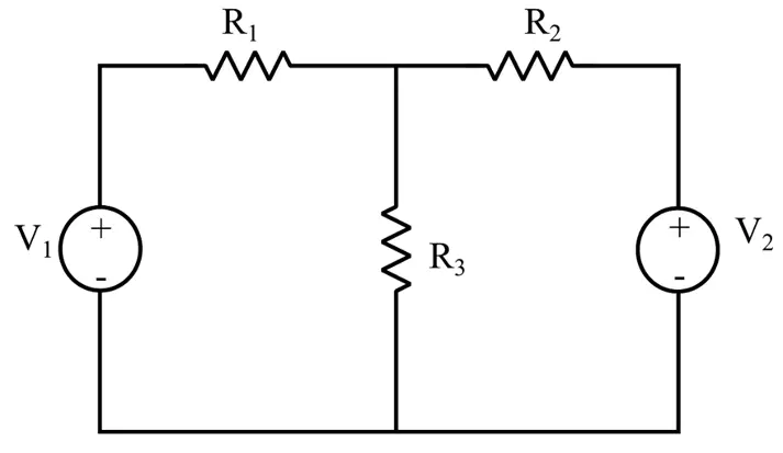
So, as per the superposition theorem, we will first find the current through the resistor R3 due to the voltage source V1 only. Then, we will find the current through the resistor R3 due to the voltage source V2 only.
While calculating the response for a particular source, all other sources in the circuit will remain inactive.
Once we got all individual responses for all the sources in the circuit. We find the final response by taking the algebraic sum of these individual responses.
Hence, the superposition theorem significantly simplifies the circuit analysis of an electric circuit containing multiple independent sources.
Steps for Solving Electric Circuit Using Superposition Theorem
The step-by-step explanation of the superposition theorem to solve an electric circuit is described below:
Step 1 – Consider only one independent voltage or current source at a time and deactivate the other independent sources. For example, deactivate an ideal voltage source by a short circuit, an ideal current source by an open circuit, or a real voltage source and real current source by their internal resistances.
Step 2 – Find the current or voltage response in the desired branch or element of the circuit for the active source.
Step 3 – Now, deactivate the source for which the response is determined, activate another source, and calculate the response for this source.
Step 4 – Repeat this process until all the sources are utilized.
Step 5 – Finally, add all the responses obtained for each source. This gives the final response (voltage or current) due to all the sources acting together.
Let’s now understand the application of the superposition theorem in circuit analysis using a solved numerical example.
Solved Example
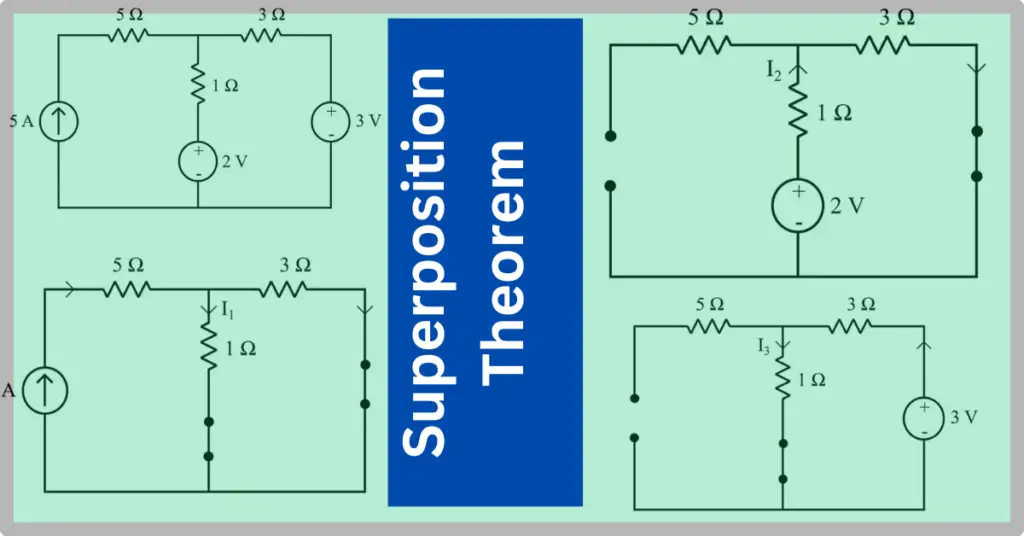
Using the superposition theorem, find the current I through a 1 Ω resistor.
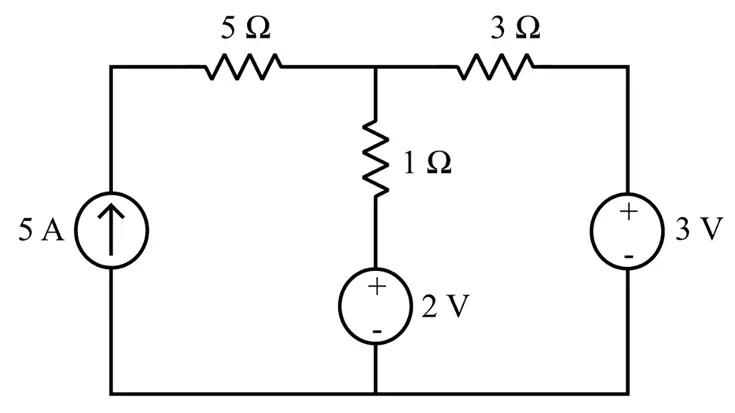
Solution – The solution of the given circuit using the superposition theorem is given below:
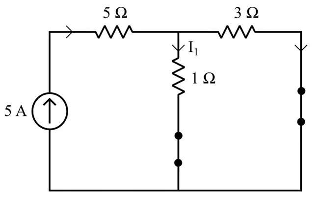
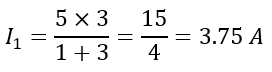
Step 1 – when 5 A current source acting alone:
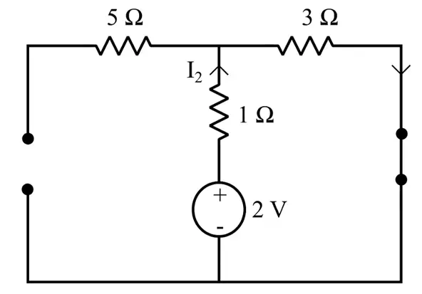
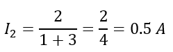
Step 2 – when 2 V voltage source acting alone:
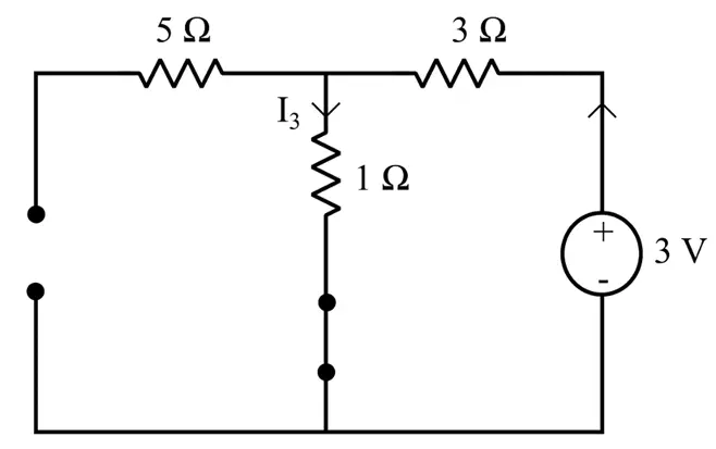
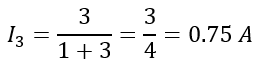
Step 3 – when 3 V voltage source acting alone:
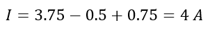
Step 4 – Applying the superposition theorem, the final response will be,
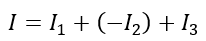
I2 is taken negative because it flows in the opposite direction of I.
Conclusion
In conclusion, the superposition theorem is a fundamental network theorem used to find an element’s response in a multi-source circuit. It is also important to remember that the superposition theorem can be applied to a circuit containing more than one independent source. This theorem simplifies the analysis of a multi-source circuit by converting it into a single-source circuit at a time. In this article, I have explained the statement, steps, and examples of the superposition theorem.
Read Next: