In this article, we will study how to perform parallel operation of DC generators. In practice, electrical power is supplied from multiple generators operated together and connected to a common or interconnected network.
Due to various technical and economical reasons, instead of using a single large DC generator, we prefer several small DC generators operated in parallel to meet the load demand. DC generators are mainly used as the backup power source.
Introduction to DC Generator
A DC generator is an electrical machine that converts mechanical energy into direct current electricity and can run the electrical loads.
A typical DC generator consists of two main components, namely stator and rotor. The stator is a stationary part carrying a field winding, and the rotor is a rotating part carrying an armature winding.
A DC generator has one more important component: a brush-commutator assembly. It performs commutation, i.e., AC-DC conversion.
Why Parallel Operation of DC Generators?
The parallel operation of DC generators is performed due to the following major reasons:
- Continuous Power Supply – The primary reason behind the parallel operation of DC generators is the continuous power supply. In cases where only a single DC generator is used in the power system, it fails. Then, the entire power system will be out of service. So, to avoid this situation, we operate many generators in parallel. If one of them gets out of service due to any reason, the remaining generators will continuously supply the load.
- Increased Power Output – The parallel operation of DC generators is also done to meet the increased power demand. This is done by combining the output of multiple generators operating in parallel.
- Flexibility in Capacity Adjustment – When multiple DC generators operate in parallel, we can easily regulate the overall capacity of the generating station by adding or removing DC generators from the parallel combination. This is an important practice to meet the varying load demands.
- Efficient Load Sharing – The parallel operation of DC generators allows for efficient load sharing among multiple generators connected in the parallel configuration. This maintains the balanced operation of the power system and improves the lifespan of DC generators.
- Reliability – The parallel operation of DC generators improves the system’s reliability. It ensures an uninterrupted power supply if one of the generators fails.
- Easy to Maintain and Repair – The parallel operation of DC generators helps facilitate generator maintenance. This is because the total load is shared among multiple generators operating in parallel. Hence, we can take any generators out of service without disturbing the entire power system.
- Better Voltage Regulation – The multiple generators operating in parallel collectively respond to any change in the load demand and maintain a stable output voltage.
Parallel Operation of Different Types of DC Generators
As we know, there are three types of DC generators, they are,
- DC Shunt Generator
- DC Series Generator
- DC Compound Generator
Let us discuss the parallel operation of each type of DC generator in detail.
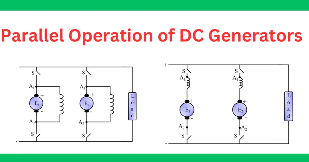
Parallel Operation of DC Shunt Generator
The connection diagram of two DC shunt generators is shown in the following figure.
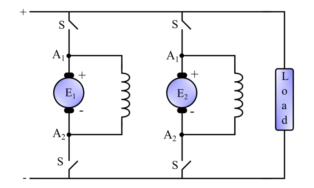
We can connect any number of DC shunt generators in parallel in the same manner.
To operate multiple DC shunt generators in parallel, we connect their positive terminal to the positive terminal of the bus bars and the generator’s negative terminals to the negative terminal of the bus bars. The busbar is a conductor made up of copper and can handle the current of all the generators connected to it.
The load is then connected across the busbar terminals, and the parallel connected generators supply power to the load.
After closing the main switch S, generator 2 is ready to be connected in parallel with the existing generator 1. However, at this point, generator 2 is not supplying any load since its induced e.m.f. is equal to the bus-bar voltage. This state is referred to as “floating,” which means that it is ready to supply power but is not currently providing current to the load.
To supply the current from generator 2, the induced e.m.f. E2 should be greater than the voltage V of the bus bars. This can be achieved by increasing the field current, which will improve the induced e.m.f. (E2) of generator 2 and start the current supply. The field of generator 1 needs to be weakened to maintain the bus-bar voltage at a constant value.
In this circuit diagram, a switch is also provided to connect or disconnect the generator from the parallel configuration.
Parallel Operation of DC Series Generator
The circuit diagram of two DC series generators operated in parallel is shown in the following figure.
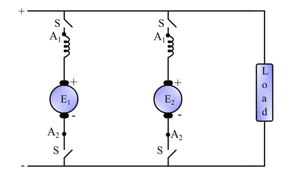
To operate two or more DC series generators in parallel, we connect their positive ends to the positive busbar and the negative ends to the negative busbar. The load is connected across the busbars.
Parallel Operation of DC Compound Generator
We can also connect two or more DC compound generators in parallel in the same way as the DC series and shunt generators.
The circuit diagram of two DC compound generators operating in parallel is shown in the following figure.
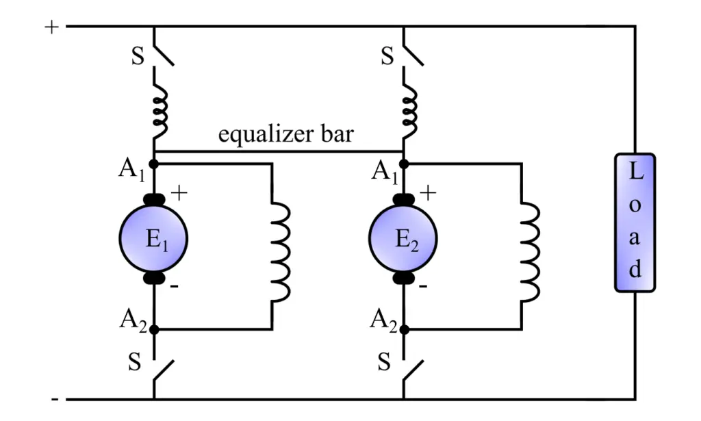
In the case of parallel operation of DC compound generators, we have to use an equalizer bar to obtain a stable parallel operation. This is because a DC compound generator has a rising characteristic. This can cause synchronization problems at the start.
Load Sharing of Parallel DC Generators
In modern electric systems, where multiple DC generators are operated in parallel, the load is shared among different generators according to their induced emf. Let us consider two DC generators operating in parallel, and their load-sharing portion will be calculated below.
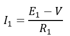
And
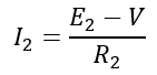
Here, E1 and E2 are induced EMFs of two generators, R1 and R2 are the armature resistances of the two generators, and V is the busbar voltage.
From these two equations, we can see that the busbar voltage can be kept constant by changing the induced emf of generators.
Conditions for Parallel Operation
For efficient operation of multiple DC generators in parallel, the following conditions must be met:
- The voltage across all DC generators in the parallel configuration must be equal. This is an essential condition for the successful parallel operation of DC generators because a significant difference in voltages can cause circulating currents among generators.
- The terminal polarity of all generators must be the same, i.e., the positive terminals of all generators are connected to the positive terminal of the parallel system, and the negative terminals of all generators are connected to the negative terminal of the system. The incorrect polarity can cause a short circuit in the system.
- The direction of rotation of all generators operating in parallel must be the same. This ensures that the induced EMFs have the same polarity and do not oppose each other.
- The DC generators operating in parallel must have a drooping voltage-current characteristic. It is important for stable load sharing and operation of parallel connected generators.
- The speed characteristics of all DC generators in parallel configuration must be the same. Maintaining a constant speed is important for variable load conditions and proper load sharing.
- For optimal parallel operation, all DC generators operated in parallel must have the same type and design. This ensures efficient and stable load sharing.
- All DC generators operated in parallel must have adequate ratings to handle the load. Underloading or overloading a generator can damage it.
Conclusion
In conclusion, in the actual electrical system, multiple DC generators are connected in a network and operated in parallel to supply the load. Parallel-operated DC generators are mostly used as backup plants in case of heavy load demands. In power systems, parallel DC generators are used to achieve continuous supply, improved efficiency, easy maintenance, etc. In this article, I have explained the parallel operation of DC generators along with the essential conditions required for parallel operation.
Related Articles: