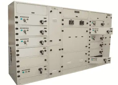
A Motor Control Center (MCC) is a metal-enclosed assembly that houses switchgear and controls for motor circuits. The term MCC stands for Motor Control Center.
A Motor Control Center panel (MCC panel)—also known as a panel MCC or motor control centre panel—is vital in electrical and industrial automation systems.
What is Motor Control Center (MCC)?
A Motor Control Center (MCC) is a centralized panel used to control multiple electric motors in an organized and efficient manner. These panels contain motor starters, circuit breakers, and other protective and control devices. MCCs are vital in industrial settings where numerous motors must be operated and managed safely.
A typical MCC panel ensures safety, simplifies maintenance, and enables centralized monitoring of motors. With advancements in automation, MCCs are now integrated with PLCs and SCADA systems for remote control and diagnostics.
MCC Panels and Their Components
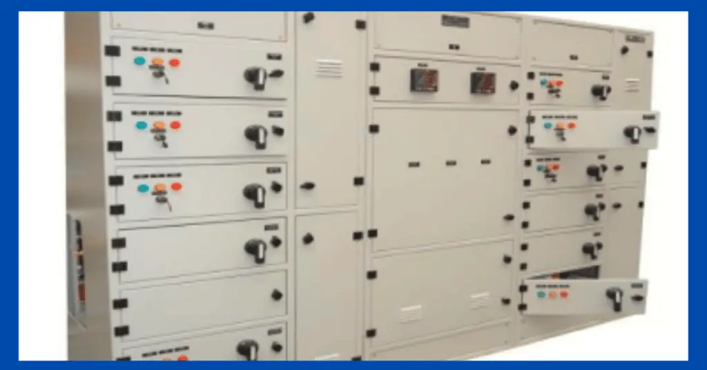
Motor Control Center (MCC) panels are essential in industrial systems for distributing power and providing centralized control over multiple electric motors.
These panels house several critical electrical components, which together ensure smooth operation, protection, and automation of motor-driven systems.
Contactor units: These electromechanical switches control the flow of electricity to motors. They enable motors to start and stop by opening or closing the circuit, either manually or via control signals.
Motor starters: These are integrated devices that combine contactors with overload protection. They allow motors to start safely and prevent damage from excessive current draw during startup and running conditions.
Overload relays: Available in thermal and electronic versions, these relays monitor motor current and disconnect the power supply in case of overload. This protects motors from overheating and prolonged stress.
Circuit breakers and fuses: These components provide short-circuit protection. Circuit breakers can be reset after tripping, while fuses must be replaced when blown.
Variable Frequency Drives (VFDs): VFDs control the speed and torque of motors by adjusting the frequency and voltage supplied. They enhance energy efficiency and support smooth acceleration and deceleration.
Soft starters: These reduce the initial inrush current during motor startup, minimizing mechanical stress and preventing voltage dips in the system.
Programmable Logic Controllers (PLCs): PLCs are compact, programmable computers that automate motor functions. They can detect faults, start or stop motors, and communicate with supervisory control systems like SCADA.
Modular compartments: MCC panels are divided into individual drawers or compartments. Each houses components for a specific motor, making maintenance easier and allowing for system expansion.
Horizontal bus: This main conductor runs horizontally through the MCC panel and distributes power from the main supply to all vertical sections.
Vertical bus: Positioned in each section, the vertical bus connects to the horizontal bus and delivers power to individual motor starter units. It ensures safe and efficient power distribution within the MCC panel.
Together, these MCC panel components form a reliable system for controlling and protecting motors in industrial and commercial applications.
Types of Starters Used in MCC Panels
MCCs may include different types of motor starters depending on motor size and application:
- Direct-On-Line (DOL) Starter – Used for small motors, offering a simple start/stop control.
- Star-Delta Starter – Ideal for reducing inrush current during motor startup.
- Soft Starter – Provides smooth acceleration by limiting voltage during startup.
- Variable Frequency Drive (VFD) – Allows precise motor speed control and energy savings.
Historical Development of MCCs
In the past:
In a production plant, there were quite a few motors of different capabilities distributed throughout the facility. Each one had to be attended to on its own board for corrective or preventive maintenance in a decentralized way. This resulted in a significant waste of time in the production process.
This decentralization led to delayed responses, disorganized maintenance, and lower productivity across industries.
Over time, electronic systems were added. Mechanical or electromechanical relays were replaced with electronic relays. This transition allowed electrical and mechanical variables to be monitored using remote controls.
Present Scenario:
MCCs have now evolved to monitor, control, and communicate operational parameters through logical programming. Depending on the application, various construction types are available.
iMCCs (intelligent MCCs) are now capable of real-time communication with PLCs and SCADA systems for better operational insights and remote access.
iMCCs enable integration with digital automation, enabling predictive maintenance, energy monitoring, and remote diagnostics. These improvements enhance reliability and reduce downtime significantly.
Purpose of Motor Control Centers
An MCC is a metal-enclosed panel designed to feed, control, and protect circuits, with motors as the primary load. Motors are controlled using starters like contactors and relays.
Each industry has unique motor control requirements, which must be considered before installation.
Key Characteristics of MCCs
- Combined units for motor control distinguish MCCs from other control centers.
- They can function in manual or automatic mode.
- Provide overload protection.
- Integration with Programmable Logic Controllers (PLC) reduces dependency on relays and timers.
- High security features for users and equipment.
- Offer fault indication, local/remote switching, and a compact modular design for ease of maintenance.
Types of Motor Control Centers (MCCs)
Motor Control Center (MCC) panels are classified based on construction, functionality, voltage level, and installation environment. Each type serves specific operational and industrial needs.
1. Based on Construction
- Fixed MCC Panels
These panels have permanently mounted components, offering high durability and stability. They are ideal for applications with consistent motor control requirements and minimal need for frequent maintenance. - Drawout MCC Panels
In these panels, components can be easily withdrawn or replaced without shutting down the entire system. This type enhances safety and simplifies maintenance during live operations. - Plug-in MCC Panels
These offer modular flexibility, allowing units to be plugged in or out as operational needs evolve. Suitable for dynamic environments that require frequent changes or upgrades.
2. Based on Functionality and Features
- Standard MCC Panels
Basic panels that include standard motor starters, circuit breakers, and overload protection devices for general-purpose motor control. - Intelligent MCC Panels (iMCCs)
These panels incorporate advanced control features like communication interfaces (Ethernet, Modbus), smart relays, and monitoring devices. They enable remote diagnostics, predictive maintenance, and SCADA/PLC integration. - Variable Frequency Drive (VFD) MCC Panels
Equipped with VFDs to regulate motor speed and torque, these panels support energy efficiency and precise process control. - Soft Starter MCC Panels
Use soft starters to minimize inrush current during motor startup. They help extend motor life, reduce electrical stress, and prevent voltage drops. - Process Motor Control Center (PMCC)
These integrate motor control with process automation systems, often used in industries like oil & gas, chemical, and manufacturing.
3. Based on Voltage Level
- Low Voltage MCCs
Designed for motors operating at 230V to 1000V, commonly used in standard industrial applications. - Medium Voltage MCCs
Suitable for motors running at voltages from 1kV to 15kV, typically used in heavy industries like power plants, mining, and large manufacturing facilities.
4. Based on Installation Environment
- Indoor MCC Panels
Installed in climate-controlled environments such as electrical rooms or factory floors. - Outdoor MCC Panels
Built with weather-resistant enclosures to withstand rain, dust, humidity, and temperature extremes. - Containerized MCC Panels
Enclosed in mobile or skid-mounted transportable containers, ideal for remote sites or temporary installations.
5. Special-Purpose MCC Panels
- Flameproof MCC Panels
Designed to withstand and contain explosions, preventing ignition of hazardous surroundings—common in oil, gas, and chemical industries. - Fire-Protected MCC Panels
Engineered to maintain operational integrity in fire conditions, protecting critical control systems.
Choosing the Right MCC Panel
Selecting the right MCC panel depends on factors such as:
- Motor control requirements
- Automation level (standard vs intelligent)
- Voltage range
- Operational environment
- Industry-specific regulations
A tailored MCC ensures optimal motor performance, safety, and long-term reliability in industrial operations.
Implementation of MCC in Industries
The use of Motor Control Centers is suitable for industries that use electric motors, such as:
- Food processing
- Chemical plants
- Pharmaceuticals
- Petroleum industries
- Power plants
- Factories
- Electronics manufacturing
In modern industries, MCCs ensure optimized motor performance, centralized control, and energy savings through automation and real-time monitoring.
Classification of MCCs
Motor Control Centers are classified based on the following:
According to Wiring Class
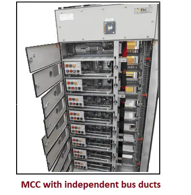
Class I
Each built-in compartment or tray has its own wiring and is isolated from other parts of the MCC. There is no interlocking between motors.
Used for simpler applications where independence between motor feeders is preferred.
Class II
Each compartment has exclusive wiring but allows interconnections with other parts of the MCC using mechanical interlocks and external control systems.
Suitable for more complex systems requiring interlocking or integrated safety features.
According to Types of Wiring
Type A Wiring
Wiring without terminal blocks for power and control circuits in the MCC.
Type B Wiring
Wiring with terminal blocks located next to or between each integrated drawer and tray in the MCC.
Type C Wiring
Individual terminal blocks for control and power are assigned to each compartment or tray.
Type C offers the highest degree of organization and ease of maintenance, making it suitable for large, complex installations.
According to Types of Construction
According to the IEC 61439-2 standard, MCCs are also classified based on their internal separation (forms of construction) using barriers or partitions.
Forms of Construction:
- Form 1: No segregation between components.
- Form 2a: External conductor terminals not separated from bus bars.
- Form 2b: External conductor terminals are separated from bus bars.
- Form 3a: Connection terminals are separated from bus bars.
- Form 3b: Connection terminals and functional units are separated from bus bars.
- Form 4a: Connection terminals share the same compartment as their functional unit.
- Form 4b: Connection terminals are in a separate compartment from the functional unit.
Higher form numbers ensure better isolation, reduced fault propagation, and increased safety—especially in critical applications like power plants and refineries.
Safety Features in Motor Control Centers
Modern MCCs are equipped with various safety features such as:
- Overload protection
- Short circuit protection
- Ground fault protection
- Interlocks and shutters to prevent accidental contact
- Emergency stop pushbuttons
These features ensure motor safety, operator protection, and compliance with electrical standards.
MCC Panel Design
Motor Control Center (MCC) panel design plays a critical role in ensuring safe, organized, and efficient control of motors in industrial settings. A well-designed MCC panel not only improves operational reliability but also simplifies maintenance, enhances safety, and allows for future scalability.
1. Design Objective
The main objective of MCC panel design is to centralize the control and protection of multiple motors from a single location. The design must accommodate the number of motors, control logic, protection schemes, environmental conditions, and future expansion possibilities.
2. Key Design Considerations
a. Load Analysis
Start by assessing the total motor load, individual motor ratings, and their starting methods (DOL, star-delta, VFD, or soft starter). This helps in selecting appropriate feeders, cable sizes, circuit breakers, and control gear.
b. Panel Size and Layout
The panel should be dimensioned to house all components comfortably, with sufficient clearance for wiring and ventilation. Components like contactors, relays, MCBs, and terminal blocks are arranged modularly for ease of access. Vertical and horizontal busbar arrangements should be considered for optimal space utilization and electrical balance.
c. Busbar Design
Busbars must be rated according to total load current with appropriate derating factors for temperature, ambient conditions, and short circuit withstand capacity. Copper or aluminum busbars are used based on current rating and budget.
d. Form of Separation
According to IEC 61439-2, panels can be designed in Form 1 to Form 4. Higher forms (e.g., Form 3b or Form 4b) provide better isolation and safety, particularly important in high-risk or critical environments.
e. Component Selection
Choose components that meet international standards (IEC, NEMA). Include contactors, overload relays, fuses or circuit breakers, current transformers, and optionally, programmable logic controllers (PLC) and VFDs for automation. Use branded components for long-term reliability.
f. Cable Management and Wiring
Internal wiring should be color-coded and tagged for easy identification. Cable trays, ducts, and sleeves are used for organized routing. Segregate power and control cables to minimize electromagnetic interference.
g. Safety Features
MCC panels must include proper earthing, interlocks, emergency stop buttons, and IP-rated enclosures based on the installation environment (indoor/outdoor). Arc flash protection, insulation monitoring, and fault alarms may be added for critical applications.
h. Accessibility and Maintenance
Design compartments or drawers in a way that allows technicians to access individual units without shutting down the entire panel. This is especially important in drawout MCCs used in continuous process industries.
3. Compliance and Testing
Before deployment, the MCC panel must undergo routine tests such as insulation resistance, high-voltage withstand, continuity, functional checks, and mechanical strength tests. Panels should conform to standards such as IEC 61439, IS 8623, and UL 845 where applicable.
4. Documentation and Drawings
Provide detailed documentation including:
- General arrangement (GA) drawings
- SLD (Single Line Diagram)
- Wiring diagrams
- Terminal schedules
- Bill of materials
- Installation and maintenance manuals
MCC Panel Wiring Diagram
A Motor Control Center (MCC) panel wiring diagram is a detailed schematic that illustrates the electrical connections between various components within the panel.
It provides a clear view of how power flows from the incoming supply to individual motor circuits through contactors, overload relays, and other control devices.
Typically, the diagram starts with the main incomer, connected to a horizontal busbar, which distributes power across the panel. Each vertical section houses individual feeders or motor starters, which include circuit breakers, contactors, and overload relays.
Control wiring connects to devices like push buttons, selector switches, and indicator lamps on the panel front.
The diagram also shows control transformers for auxiliary supply and terminal blocks for external connections. In advanced MCCs, components like Variable Frequency Drives (VFDs) or Programmable Logic Controllers (PLCs) are included, and their control wiring is shown to demonstrate communication between motors and automation systems.
Proper interpretation of the wiring diagram is crucial for installation, troubleshooting, and maintenance. It ensures safety and operational efficiency by highlighting correct connections, wire sizes, and protection schemes.
Overall, the MCC panel wiring diagram serves as a blueprint for both engineers and technicians working with motor control systems.
Key Differences Between MCC and PCC Panels
In industrial electrical systems, MCC (Motor Control Center) and PCC (Power Control Center) panels play crucial roles. While they may appear similar in construction, they serve distinct functions and are designed for different applications.
Understanding the difference between MCC and PCC panels helps in selecting the right control system for industrial needs.
| Feature | MCC Panel | PCC Panel |
| Primary Function | Motor control and protection | Power distribution and control |
| Main Components | Starters, contactors, overload relays | ACBs, MCCBs, meters, protection relays |
| Load Type | Motor loads | Electrical loads (motors + others) |
| Installation Location | Near motor locations | Near transformer or main incomer |
| Control Scope | Controls individual motor circuits | Controls entire power network |
| Automation Integration | Often integrated with PLC/VFD systems | Less frequent but possible |
Advantages of Motor Control Centers
Some major advantages of using MCC panels for motors include:
- Group motor starter systems and power distribution within the same board.
- Enable effective supervision of multiple motor units.
- Centralize starter systems.
- Reduce costs as all feeder lines are routed to a single location.
- Promote organization and order between the starter systems and motors.
- Enhance user safety.
- Provide protection against electrical failures.
- Allow flexible modification of motor functions.
Conclusion
A well-designed Motor Control Center is essential for modern industries where motor reliability, centralized control, and operator safety are critical. Proper classification and implementation of MCCs ensure operational efficiency and provide scalability for future expansion.
Frequently Asked Questions
The full form of MCC panel is Motor Control Center. It is a metal-enclosed panel designed to control and protect electric motors in industrial and commercial systems.
An MCC panel centralizes the control of multiple electric motors. It houses components like contactors, overload relays, and circuit breakers to ensure safe and efficient motor operation.
An MCC (Motor Control Center) panel is used for motor control, while a PCC (Power Control Center) panel is used to distribute power to various loads in a facility.
Related Articles: