A magnetic contactor is an electrically operated switching device used to control motors and other high-power electrical loads. It uses an electromagnetic coil to open or close its main contacts, allowing a relatively small control signal to switch a much larger load current. Magnetic contactors are widely used in motor starters, industrial automation, HVAC systems, and electrical control panels.
What is a Magnetic Contactor?
A magnetic contactor is an electromechanical device used to establish or interrupt the flow of current in power or control circuits.
It can be used to switch the electrical supply to a load or installation. When the magnetic contactor coil receives the required control voltage, the electromagnetic field attracts the armature and changes the position of the contacts. The contactor therefore has two basic states: a de-energized state, in which the contacts remain in their normal position, and an energized state, in which the contacts change position to connect or disconnect the load circuit.

Magnetic Contactor Working Principle
A magnetic contactor operates through the interaction between an excitation coil, magnetic core, armature, and electrical contacts. When the control supply is applied to the coil, it produces an electromagnetic field. The resulting magnetic force attracts the moving armature toward the fixed core and overcomes the force of the return springs.
As the armature moves, it mechanically operates the main and auxiliary contacts. The main contacts close to connect the electrical supply to the load, while the auxiliary contacts can be used in control, interlocking, signaling, and automation circuits.
When the control supply to the coil is removed, the electromagnetic field collapses. The return springs then move the armature back to its original position, causing the contacts to open and disconnect the load from the supply. This allows the contactor to remotely control electrical loads using a relatively small control signal.
Parts of Magnetic Contactor
A magnetic contactor consists of several important parts that work together to switch and control electrical loads. The major components include the electromagnet, core, armature, coil, main contacts, and auxiliary contacts.
Electromagnet
The magnetic circuit comprises a fixed core, a moving armature, and a shading ring, the latter being required for electromagnets powered by alternating current. The magnetic circuit includes a small air gap in the closed position to prevent residual magnetic flux from holding the moving armature in position.
Core
The core is made of laminated silicon steel sheets to reduce eddy current losses caused by circulating currents. It provides a path for magnetic flux and supports the excitation coil.
Armature
The armature is the moving part of the electromagnet. When the coil is energized, the magnetic force attracts the armature toward the core. The movement of the armature operates the main and auxiliary contacts.
Coil
The excitation coil is responsible for producing the magnetic field required to operate the contactor. The force of attraction of the electromagnet depends on the magnetic flux generated by the coil. To produce this flux, the excitation coil is housed on one of the limbs of the electromagnet core and is generally wound on an insulating former.
Enameled copper wire is commonly used for the construction of the coil because of its good electrical conductivity and insulating coating. The coil is designed according to the required operating conditions and is properly insulated from the core.
The coil specifications are normally marked at a visible location and include the rated voltage, current type (AC or DC), and frequency in the case of an AC coil.
The coil terminals are labeled A1 and A2. The coil energizes the contactor’s electromagnet and is available in various control voltage ratings, such as 24 VDC, 24 VAC, 110 VAC, 240 VAC, and 415 VAC.

Main Contacts
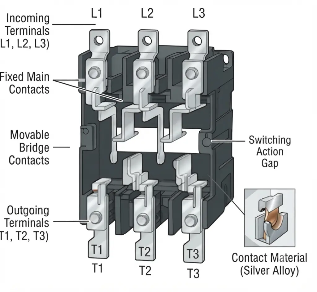
The main contacts carry and switch the load current. In a three-phase contactor, the incoming terminals are commonly identified as L1, L2, and L3, while the corresponding outgoing terminals are T1, T2, and T3. When the contactor operates, these contacts connect or disconnect the electrical supply to the load.
Depending on the number of current paths, a contactor may have two-pole, three-pole, four-pole, or other configurations, with the contacts operating simultaneously.
Auxiliary Contacts
Auxiliary contacts are used mainly in control, interlocking, signaling, and automation circuits. They are generally available as Normally Open (NO) and Normally Closed (NC) contacts. These contacts can be used to provide contactor status feedback or establish control logic.
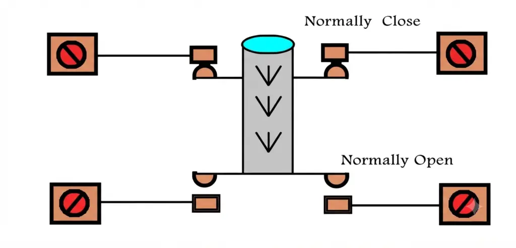
A Normally Open (NO) auxiliary contact remains open when the contactor coil is de-energized and closes when the coil is energized. A Normally Closed (NC) auxiliary contact remains closed when the contactor coil is de-energized and opens when the coil is energized.
Auxiliary contacts are commonly used for self-holding circuits, control logic, electrical interlocking, signaling, and contactor status indication.
When the contactor coil is energized, the armature moves and operates both the main and auxiliary contacts. The main contacts switch the load circuit, while the auxiliary contacts perform the required control or signaling functions.
Types of Magnetic Contactors
There are two main types of magnetic contactors:
- AC Magnetic Contactor
- DC Magnetic Contactor
Categories of AC Magnetic Contactors
AC magnetic contactors are classified into different utilization categories based on the type of AC load and its operating conditions.
AC-1 Magnetic Contactor
The AC-1 magnetic contactor category applies to AC loads with a power factor of at least 0.95. These loads are mainly non-inductive or slightly inductive, and interruption is relatively easy.
AC-2 Magnetic Contactor
The AC-2 magnetic contactor category is intended for controlling wound-rotor induction motors. These contactors are suitable for motor applications where the motor may require switching under operating conditions associated with starting and stopping. The AC-2 utilization category is particularly associated with motors having a slip-ring and wound-rotor arrangement.
AC-3 Magnetic Contactor
The AC-3 magnetic contactor category applies to squirrel-cage induction motors. In this category, disconnection generally occurs while the motor is running at full speed, and the breaking current is approximately the rated current.
AC-4 Magnetic Contactor
The AC-4 magnetic contactor category is used for starting and stopping squirrel-cage induction motors under demanding operating conditions. It is suitable for applications involving jogging, inching, plugging, and reversing of motors.
Categories of DC Magnetic Contactors
DC-1 Magnetic Contactor
The DC-1 magnetic contactor category applies to DC loads that are mainly non-inductive or slightly inductive. It is suitable for applications where the load does not produce significant inductive effects during switching. This category is commonly associated with general-purpose DC loads where the making and breaking of the circuit is relatively straightforward.
DC-2 Magnetic Contactor
The DC-2 magnetic contactor category applies to DC shunt motors, where disconnection occurs while the motor is running at full speed. It is intended for switching applications involving DC shunt motors under normal operating conditions. The contactor must be selected according to the motor’s rated voltage, current, and switching duty.
DC-3 Magnetic Contactor
The DC-3 magnetic contactor category is used for starting and stopping DC shunt motors. It also applies to operations such as stopping during starting, jogging, reversing, and dynamic braking.
Precautions When using Magnetic Contactor
Under normal operating conditions, a magnetic contactor should provide reliable service when it is correctly selected for the application and operated within its rated limits. Contact wear and coil failure are among the common problems that can affect contactor performance.
Excessive current flowing through the magnetic contactor can cause the main contacts to overheat, weld, or stick together. To improve system protection, a magnetic contactor should be used with appropriate protective devices such as overload relays and fuses or circuit breakers.
The contactor should also be selected according to the load current, rated voltage, utilization category, control-coil voltage, and switching duty. Regular inspection of the contacts, coil, terminals, and associated protection devices can help identify problems before they lead to contactor failure.
Advantages of Magnetic Contactor
Magnetic contactors offer several advantages in the control and automation of electrical machines and equipment, including:
- Remote control: A machine can be completely controlled from various control points or stations.
- High-current switching: Electrical circuits carrying high currents can be controlled using a relatively small control circuit.
- Improved safety: Operators can control motors and other electrical loads from a safe distance, reducing exposure to high-voltage or high-current equipment.
- Remote operation: Switching operations can be performed from locations away from the motor or other electrical loads.
- Low control power: The control devices can operate with relatively low currents and voltages while controlling higher-power circuits.
- Automation: Magnetic contactors can be integrated into control systems to operate and automate equipment and machines involved in complex processes.
Applications of Magnetic Contactors
Magnetic contactors are widely used for the remote switching and control of motors, lighting systems, and other electrical loads. They allow relatively small control signals to operate higher-current power circuits and are therefore commonly used in industrial and commercial electrical systems.
Magnetic Motor Starter
A magnetic motor starter combines a magnetic contactor with an overload relay to provide both motor switching and overload protection. The contactor controls the motor’s power supply, while the overload relay detects excessive current and interrupts the control circuit when the motor experiences an overload condition.
Overload relays may use thermal heaters or electronic sensing elements to detect excessive motor current and protect the motor from prolonged overload conditions.
Lighting Control
Magnetic contactors are also used for the remote or centralized switching of lighting loads. They can control relatively large groups of mercury, fluorescent, tungsten, or LED lighting circuits from a local or remote control station. This arrangement is useful where several lighting circuits need to be switched ON or OFF from a common control point.
Motor and Load Control
A magnetic contactor allows large motors and electrical loads to be controlled using a relatively small control switch or push button. This provides convenient remote operation and reduces the amount of power required in the control circuit.
Three-Phase Motor Control
Magnetic contactors are commonly used for switching the three-phase supply of induction motors. They are also an important part of DOL and star-delta motor starters, where multiple contactors can be used to control different operating states of the motor.
Control and Signaling
The auxiliary Normally Open (NO) and Normally Closed (NC) contacts of a contactor can be used for control logic, electrical interlocking, status indication, and signaling. These contacts allow the contactor to be integrated into automatic control systems.
Power Interruption and Automatic Control
When the control supply to a contactor is interrupted, the coil becomes de-energized and the main contacts open, disconnecting the load. In many motor-control circuits, this prevents the motor from automatically restarting when the power supply returns, unless a new start command is given. This feature can help provide protection against unintended motor restarting.
Conclusion
A magnetic contactor is an important electromechanical switching device used to control motors, lighting systems, and other electrical loads. It operates on the principle of electromagnetism, where energizing the coil produces a magnetic field that moves the armature and changes the position of the main and auxiliary contacts.
Magnetic contactors are available for both AC and DC applications, with different utilization categories designed for specific load and switching conditions. The main contacts handle the load current, while auxiliary NO and NC contacts are used for control, interlocking, signaling, and automation circuits.
With their ability to provide remote control, high-current switching, and integration with protection and automation systems, magnetic contactors are widely used in industrial and commercial electrical installations. Proper selection based on load current, voltage, utilization category, coil voltage, and switching duty is essential for safe and reliable operation.

Read Next