Impedance opposes the current in the AC circuit. The impedance is formed in the AC circuit because of the resistance and reactance of the circuit components like resistors, inductors, and capacitors.
In this article, we will study the concept of impedance, complex impedance, its unit, and the formula for RL, RC, and RLC circuits. Here, we will also derive the expressions of impedance for different types of AC circuits.
In AC electric circuits, impedance is a parameter that describes the electrical opposition to the flow of alternating current through the circuit. In simple terms, Impedance is the opposition to the AC or alternating current. The role of impedance in an AC circuit is the same as that of a DC circuit’s resistance.
Definition of Impedance
In AC electric circuits, the impedance is defined as the total electrical opposition offered by the circuit elements to the flow of alternating current through the circuit. The impedance is frequency-dependent because the reactance of the inductor and capacitor varies with a change in the frequency.
The reactance of the inductor is inversely proportional to the frequency, and the reactance of the capacitor is inversely proportional to the frequency. Therefore, the current flowing in an AC circuit that has circuit elements like inductor and capacitor lags or leads the applied voltage, depending on the net reactance of the circuit.
The phase angle of pure inductive and capacitive components is always 90 degrees out-of-phase with the resistive component. Therefore, the circuit’s total impedance can not be a simple algebraic sum, and we need to add the vector quantity to get the total impedance.
Generally, Impedance is denoted by the symbol ‘Z’. It is important to note that it is a complex quantity with both magnitude and angle. In other words, it has two parts, namely, the real part and the imaginary part. Therefore, it is also referred to as the complex impedance.
Unit of Impedance
The SI unit of the impedance is Ohm, the same unit as of resistance. The symbol of this unit is given in the below image.

Components of Impedance
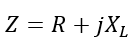
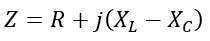
Impedance has two main components, namely resistance (R) and reactance (X), i.e.
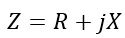
Where j is an imaginary operator.
In the case of impedance, the resistance is known as a real part of the impedance, and it dissipates electrical energy in the form of heat. On the other hand, the reactance is considered the imaginary part of the impedance and stores electrical energy in the form of a magnetic field or electric field.
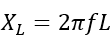
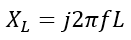
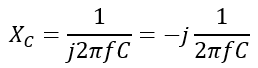
The reactance components can be inductive reactance (XL) and capacitive reactance (XC), depending on the presence of the inductor and capacitor.
Where,
And,
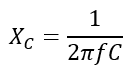
Where f is the supply frequency.
Magnitude and Angle of Complex Impedance
The complex impedance of an AC circuit is given by,
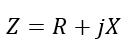
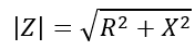
Thus, the magnitude of the complex impedance is given by,
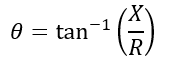
The angle of the impedance is given by,
After getting an overview of impedance and complex impedance, let us now derive the expression of impedance for different circuit configurations.
Impedance Formula
The impedance formula and calculation for series and parallel RL, RC, RLC circuits are given in the subsequent part of this article.
RL Circuit
A typical RL circuit is depicted in the following figure.
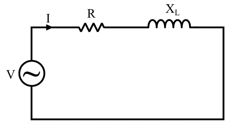
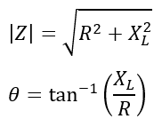
This circuit has two components: a resistance (R) and an inductive reactance (XL). Therefore, the impedance of this circuit is given by,
The magnitude and angle of this impedance is given by,
RC Circuit
The following figure shows an RC circuit.
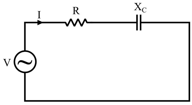
Similar to the RL circuit, it also has two components: a resistance (R) and a capacitive reactance (XC).
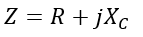
Therefore, the impedance of this circuit is given by,
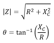
The magnitude and angle of this impedance is given by,
RLC Circuit
An RLC circuit has three components: a resistance (R), an inductive reactance (XL), and a capacitive reactance (XC).
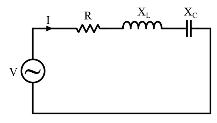
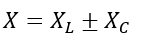
Therefore, the combined reactance of the RLC circuit is equal to the algebraic sum of inductive reactance and the capacitive reactance, i.e.
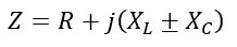
Hence, the impedance of the RLC circuit is given by,
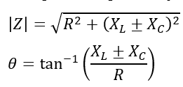
The magnitude and angle of this impedance is given by,
Parallel RL Circuit
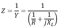
The impedance of a parallel circuit is computed with the help of admittance (Y) of the circuit.
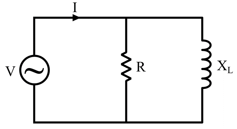
For example, consider a parallel RL circuit, then its admittance is given by,
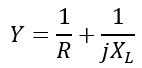
Hence, the impedance of this circuit will be,
We can extend this expression to all kinds of parallel AC circuits.
Now, let us consider some numerical examples to understand how to calculate the impedance of a given circuit.
Solved Problems
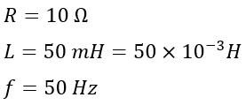
Numerical Example (1) -An RL circuit has a 10 Ω resistor and 50 mH inductor connected in series. Calculate the impedance and phase angle of the circuit at 50 Hz frequency.
Solution – Given,
Therefore, the inductive reactance will be,
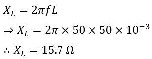
Hence, the impedance of the RL circuit is,
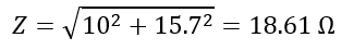
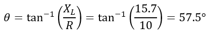
The phase angle of the circuit is,
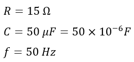
Numerical Example (2) – An RC circuit has a 15 Ω resistor and 50 µF capacitor connected in series. Calculate the impedance and phase angle of the circuit at 50 Hz frequency.
Solution – Given,
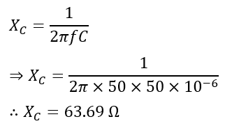
Therefore, the capacitive reactance will be,
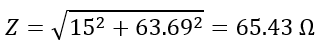
Hence, the impedance of the RC circuit is,
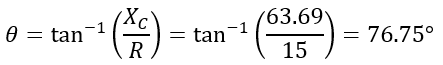
The phase angle of the circuit is,
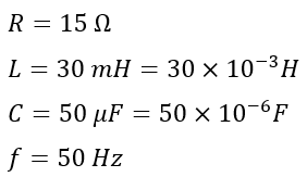
Numerical Example (3) – An RLC circuit has a 15 Ω resistor, 30 mH, and 50 µF capacitor connected in series. Calculate the impedance and phase angle of the circuit at 50 Hz frequency.
Solution – Given,
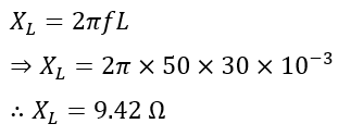
The inductive reactance will be,
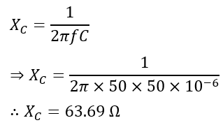
And, the capacitive reactance will be,
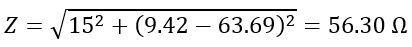
Hence, the impedance of the RLC circuit is,
Since,
And,
Therefore,
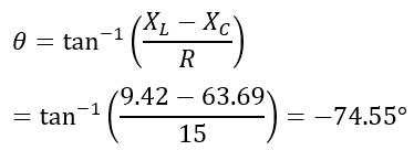
The phase angle of the circuit is,
This is all about impedance and complex impedance. We have explained the concept of impedance, complex impedance, its units, and the formula for different circuit configurations and solved numerical examples.
Read Next: