Current transformer (CT) secondary grounding is essential for safety, relay accuracy, and avoiding equipment damage. This article explains why CT secondary is grounded, how CT earthing works, and why CT secondary is shorted and grounded at only one point as per IEEE and ANSI standards.
Why Is CT Secondary Grounded?
According to the ANSI guide, the IEEE standard specifies the current transformer grounding practices. The grounding of the current transformer is critical from the perspective of safety and the correct operation of the protective relays.
CT secondary earthing ensures that dangerous voltages do not appear on secondary terminals and prevents open-circuit hazards.
As per the grounding standard of the current transformer, the current transformer’s secondary circuit should be connected to the station ground at only one point. This holds true irrespective of the number of current transformer secondary winding connected to the circuit.
If the current transformer has sets of three secondary winding, the individual winding should not be connected to the ground.
The circuit formed with the sets of the secondary winding of the current transformer must be connected at only a single point, at the neutral formation point of the CTs.
The single grounding of current transformers eliminates the problems of the voltage generated at different ground points of the current transformer.
IEEE Guidelines on CT Earthing
According to IEEE C57,13.3-2014-IEEE Guidelines for grounding of instrument transformer
- The secondary of the current and potential transformer must be grounded
- The secondary of the CTs must be grounded at a single point.
This is the recommended practice for safe and effective CT secondary connection.
Effects of Multiple Grounding Points
If the current transformers are grounded at multiple ground points, the normal current does not create any problems.
However, during a fault condition, the magnitude of potential rise at the different ground points of the current transformer will be different.
The rise in ground potential may not accurately represent the primary current, and the relay may trip even if there is no fault in the protection zone.
Tripping a differential relay due to a fault external to the zone of protection is one of the more popular nuisance trips.
Incorrect Method: CT Grounding at Two Points
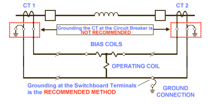
Current transformer grounding diagram should always avoid multiple earthing points.
If each current transformer is grounded separately during fault conditions, the potential rise for CT1 and CT2 secondary may be different, and the relay may get tripped with this even if there is no fault in the protection zone.
To avoid this problem, the recommended grounding method is to install a single ground point at one point, either at the switchboard or at the relay panel.
Correct CT Secondary Grounding Practice
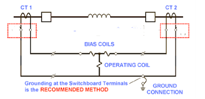
The point of grounding in the instrument transformer secondary circuit should be at the control board or the first point of application.
This applies whether you’re grounding CT secondary in a breaker or relay panel.
If the protection relay is mounted in the breaker, the neutral point of both CTs must be grounded at one point.
If the protection relay is mounted in a separate location, the star connection can be made in the breaker, but the neutral points of the CTs must be grounded at a single point at the relay end.
Relay Operation and Differential Protection Reliability
The differential relay must trip only when the fault is internal to the protective zone.
If the CTs are grounded at different points, the fault external to the protective zone may raise the current transformers’ ground potential for differential protection.
In this situation, the ground potential rise at one of the CTs may be more than the ground potential rise at the other CT, and this difference of potential at the secondary of the current transformer may cause spurious tripping of the differential protection relay.
In case of an external fault, there would be a slight difference in the secondary voltage of CTs as the rise in the ground potential would be the same for both the CTs & there would be no spurious tripping.
Conclusion: Always Ground CT at a Single Point
The reliable operation of the differential protection can be ensured if the CTs are grounded at one point: the star point of CTs.
This is why CT secondary is shorted and earthed only once—to maintain protection reliability and avoid relay malfunctions.
Frequently Asked Questions
To prevent dangerous voltage rise, ensure safety, and enable accurate protection relay operation.
The secondary may float to high voltage, causing insulation failure, relay malfunction, or equipment damage.
Ground only one point of the secondary circuit—usually at the star point near the relay panel.
No. Grounding at multiple points can cause potential differences and incorrect differential protection relay operation.
Realated Articles: