This article describes the construction and working principle of a synchronous generator (also called an alternator). So, let us start with the basic introduction of the synchronous generator.
Synchronous Generator
A synchronous generator also referred to as an AC generator or alternator, is an electromechanical energy conversion device that converts mechanical energy from sources like engines, turbines, etc. into electrical energy in the form of alternating current (AC).
It is called an alternator because it produces alternating current electricity, and it is called a synchronous generator because it is necessarily driven at synchronous speed (NS) to generate electricity at the desired frequency.
Though a synchronous generator can be single-phase or three-phase, due to some technical and economic benefits, three-phase synchronous generators are the most widely used.
Construction of Synchronous Generator
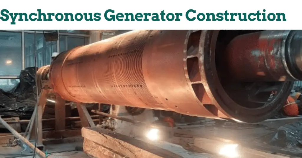
The construction of a synchronous generator (alternator) is shown in figure-1.
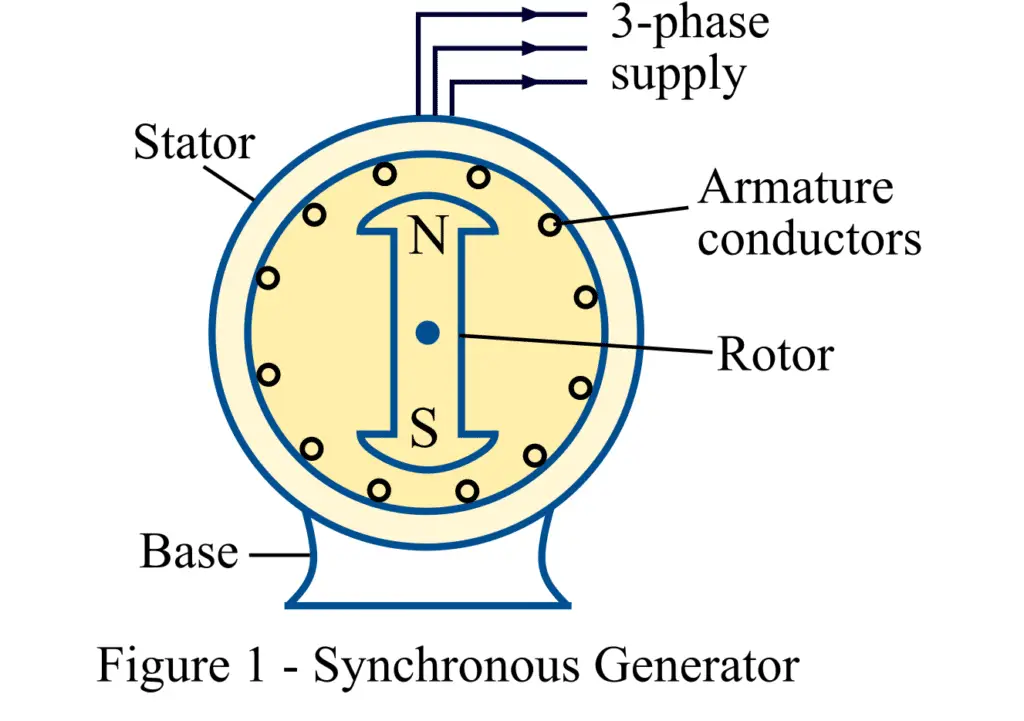
Like any other rotating electrical machine, a synchronous generator also has two main parts, namely, the stator and rotor, as shown in the above figure. As the name implies, the stator is the stationary part of the synchronous generator, while the rotor is the movable part of the generator.
Stator Construction of Synchronous Generator
In the synchronous generator, the stator carries the armature winding placed in the slots cut on the inner periphery of the stator core.
The stator of the alternator includes several parts like the frame, stator core, stator or armature windings, stator terminal box, neutral CT, and its terminal box and cooling arrangement. The following are the features of the stator or armature of the synchronous generator.
- The stator frame of a small-sized alternator is made up of cast iron, and of a large-size alternator, the stator’s frame is made up of welded steel.
- The stator core is assembled with high-grade silicon content steel laminations is used in the stator core. The steel core laminations reduce the hysteresis and eddy-current losses in the stator core.
- The stator slots are cut on the inner periphery of the stator core. The stator slots hold the armature winding.
- The armature winding of the synchronous generator is star-connected, and thus, it needs less insulation.
- The winding of each phase is equally distributed over several slots. The distributed armature winding produces sinusoidal EMF.
Rotor Construction of Alternator
The rotor carries the field winding, which is excited from an external DC source to produce a stationary rotor magnetic field. The synchronous generator’s rotor core is made of laminated sheet steel to reduce power loss due to eddy currents and hysteresis.
The rotor core is keyed to a rotor shaft, which is connected to a prime mover like a turbine, engine, etc. This whole internal assembly is enclosed in a hollow cylindrical cover to provide mechanical strength to the machine and protect it from external impacts.
In synchronous generators, the following two types of rotor constructions are used:
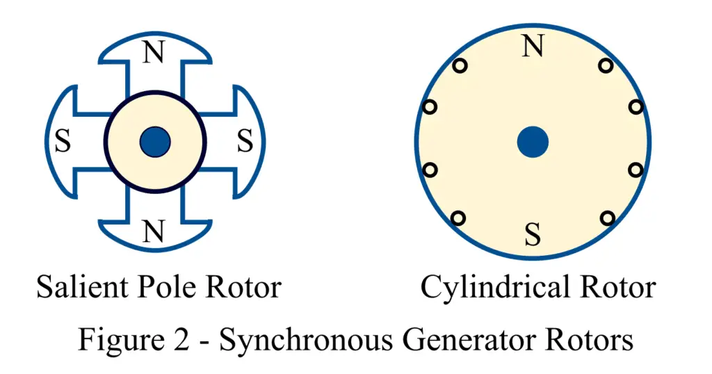
Salient Pole Rotor
In the case of the salient pole rotor, the rotor poles are projected outward, i.e., projected poles are fixed on a large circular metal frame, as shown in Figure 2. Hence, the poles of a salient pole rotor project out from the surface of the rotor core. Each field pole winding is connected in the series connection, and it is energized by the DC voltage of a DC exciter. The arrangement of the field winding is done in such a way that the adjacent poles have opposite polarity.
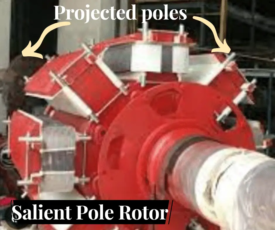
The salient pole-type rotor design is suitable for low and medium speeds (from 120 to 400 RPM). Diesel engines or water turbines drive these alternators. The reasons for the salient pole rotor’s low-speed operation are as follows.
- The salient pole-type rotor cannot withstand heavy mechanical stresses because its poles are projected. Therefore, it can not be operated at high speeds.
- At high speeds, the salient pole-type rotor causes heavy windage loss and noise.
The salient pole rotor has a large diameter to accommodate more poles. Therefore, a salient pole rotor has a larger diameter and short axial length.
Cylindrical Rotor
Cylindrical rotor construction is made up of a smooth circular piece of metal, where the outer periphery slots are cut to place rotor windings; refer to Figure 2. This rotor construction is best suited for high-speed synchronous generators.
Hence, from the constructional discussion of the synchronous generator, we can conclude that the synchronous generator consists of a stationary armature and a rotating magnetic field system.
A cylindrical rotor alternator has a comparatively long axial length and a small diameter. The other names of the cylindrical rotor alternators are turbo-alternators or turbo-generators. They are always installed in a horizontal configuration.
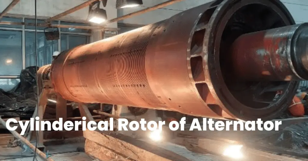
The following are the features of the cylindrical rotor.
- The poles of the cylindrical rotor can not be physically seen as in the salient pole rotor.
- In about 66 % of the outer periphery of the cylindrical rotor, slots are cut uniformly at regular intervals, and all the slots are parallel to the rotor shaft.
- These slots house field windings and receive DC supply for winding excitation. The field winding is a distributed type.
- The one-third un-slotted portion forms the pole faces.
- As we can see in the figure, the poles of the cylindrical rotor are not projected and are non-salient. Therefore, poles do not project outside of the rotor surface.
- Solid forgings of high-grade nickel-chrome-molybdenum steel are used to form a cylindrical rotor.
The cylindrical type rotor construction is suitable for high-speed applications, and they are widely used in high-speed machines for 1500-3000 RPM( 4 poles and 2 poles) alternators. These alternators are driven by a steam turbine. The cylindrical rotor is used for high-speed applications because of the following reasons.
- At high speed, the parts of the rotor experience more mechanical force, and it is a must that all the parts of the rotor should be capable of sustaining the force. The cylindrical type rotor construction can sustain a greater mechanical strength because of its cylindrical type construction, and it also permits more accurate dynamic balancing.
- The air gap in the cylindrical rotor is uniform and as a result, it has a noiseless operation at high speeds.
- The uniform air gap and distributed winding arrangement of the cylindrical rotor produce uniform flux distribution around the periphery of the rotor. Therefore, it produces better EMF and nearly a sine wave.
Now, let us discuss the working principle and operation of the synchronous generator.
Working Principle of Synchronous Generator
The working principle of a synchronous generator is the same as a DC generator, i.e., the fundamental principle of electromagnetic induction. This principle states that when the magnetic flux linking a conductor or coil changes, an electromotive force (EMF) is induced in the conductor or coil.
In the synchronous generator, the rotor winding (field winding) is excited from a source of dc power to develop alternate N and S poles in the rotor. Now, this rotor is rotated in an anticlockwise direction with the help of a prime mover such as a turbine or engine. The speed of the rotation of the rotor is constant and is equal to synchronous speed.
The rotating magnetic field of the rotor cuts the armature conductors. Consequently, electromagnetic induction induces an EMF in the armature conductors. As the armature conductors are cut by alternate N and S poles in each rotation, the induced EMF becomes alternating in nature. The induced EMF in the armature is the result of the relative motion between the conductor and the field. The induced voltage is a sinusoidal wave.
The frequency of this alternating induced emf is given by,
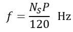
Where P is the number of rotor poles and NS is the synchronous speed in RPM (revolution per minute).
The direction of this induced emf is determined by Fleming’s Right-Hand Rule (FRHR).
Hence, this is all about the construction and working principle of a synchronous generator.