The synchronous motor construction is similar to that of a synchronous generator. A synchronous motor is a type of electric motor that has two separate sources of excitation, making it a doubly-excited machine, and it runs at synchronous speed. In this article, we will discuss the construction and working principle of a synchronous motor.
What is a Synchronous Motor?
The synchronous motor runs at a synchronous speed. The synchronous speed is the constant speed at which the motor delivers torque to the load. Synchronous motors are one of the most widely used AC motors, along with induction motors.
The general term used is “Synchronous machine,” as the same machine can work as a motor and a generator if and when required. Synchronous generators are also called alternators because they generate the alternating current. These are used in power plants to generate electricity, whereas the synchronous motor is used mostly for driving loads and correcting the power factor.
Construction of a Synchronous Motor
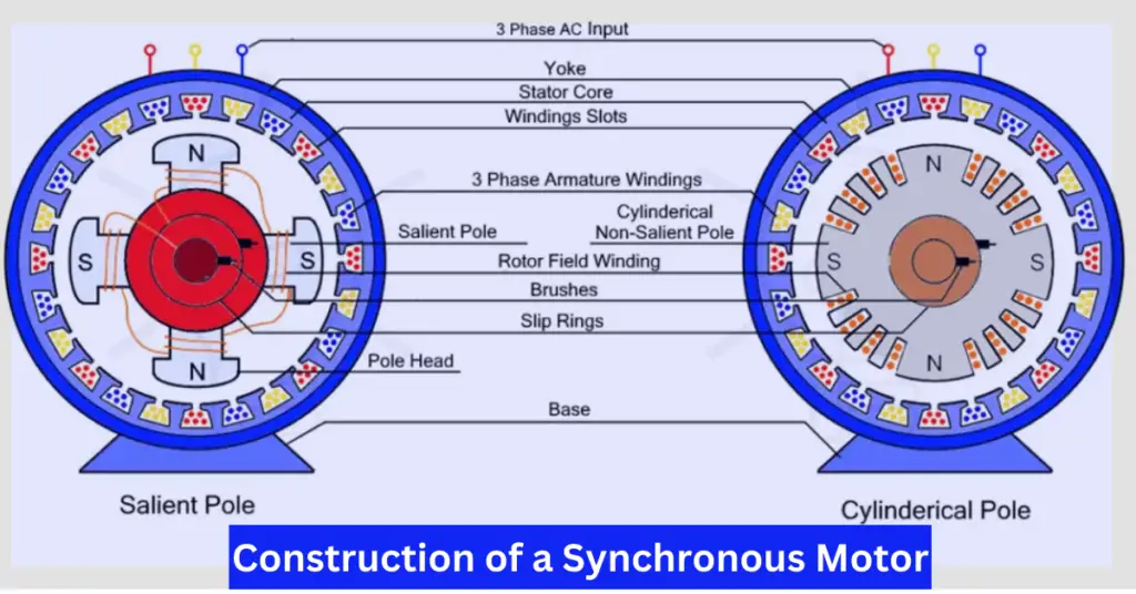
The construction of a synchronous motor is shown in the diagram below.
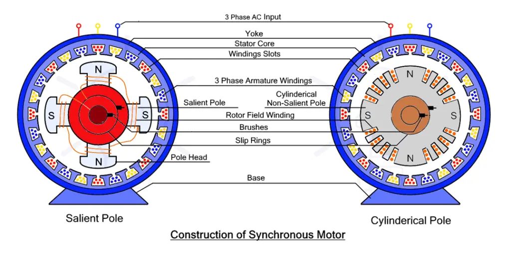
A synchronous motor has two important sections – the stator and the rotor. Both of them are separated by an air gap. The stator is the outer stationary frame, which places the stationary supply side windings. The rotor, on the other hand, is the rotating part of the motor which places the rotor windings.
Unlike a DC motor, the stator and the rotor are physically separated by an air gap. The stator and the rotor remain coupled magnetically, which results in the motor’s operation. Let’s look at each of these parts in more detail.
Stator:
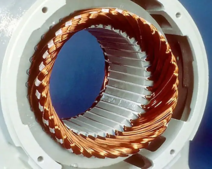
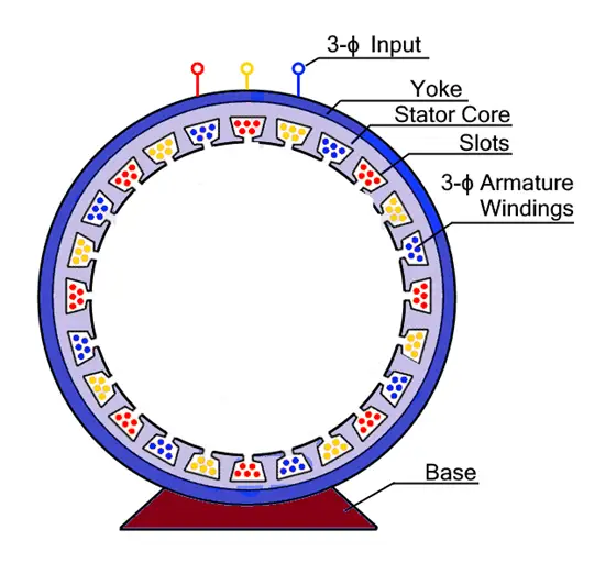
The stator is the stationary part of the motor, which is made up of thin laminated sheets of cast iron, which is ferromagnetic (having good magnetic quality). This helps reduce core losses, i.e., hysteresis and eddy current losses.
As evident from the image above, the stator holds the three-phase armature windings placed in its axial slots. When the motor is supplied through a three-phase power source, the armature windings generate the three-phase rotating magnetic field in the air gap.
Rotor:
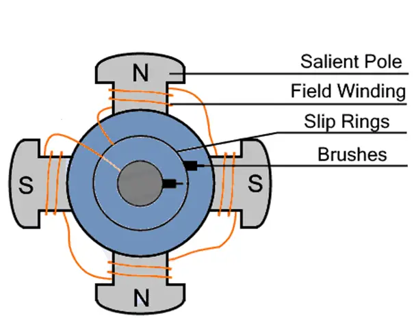
The rotor is the rotating part of the motor. It holds the rotor field winding, which generates the magnetic poles. The field winding on the rotor is excited by a separate DC source with the help of slip rings and brushes. The generated poles on the rotor help it achieve the synchronous speed, which is the speed of the rotating magnetic field. Once the motor achieves the synchronous speed, the DC source is cut off from the rotor windings. Usually, the DC source is a DC generator coupled to the shaft of the motor.
In the case of a synchronous motor, the rotor is of two types – Cylindrical Rotor and Salient pole rotor. The following sections explain the construction of the cylindrical and salient pole rotor of a synchronous motor.
Cylindrical Rotor:
As the name says, the rotor, in this case, is cylindrical with slots on its face to hold the rotor field windings. The un-slotted part of the rotor forms the rotor poles. The diameter of the rotor, in this case, is relatively smaller than that of the salient-pole rotor. The axial length is longer.
In the case of a cylindrical rotor machine, the rotor is smooth and symmetric, which results in a simple and smooth distribution of the air-gap magnetic field flux. Moreover, the smooth rotor design makes it ideal for high-speed operations. A cylindrical rotor machine is used in thermal power plants for the generation of electricity. It is costlier than its salient-pole counterpart.
Salient Pole Rotor:
The term ‘salient’ means projecting outward. In the case of a salient pole rotor machine, the rotor has projecting or protruding poles facing the stator armature windings. The rotor field winding is placed on each of these protruding poles.
In a salient pole rotor machine, the number of poles is higher. This machine is not suitable for high-speed operation as it has protruding poles, which can result in higher windage loss as well as wear and tear due to centrifugal force acting on it under high-speed operation. The magnetic field distribution in the case of a salient pole machine is complex and non-uniform, which may result in higher harmonics. Salient-pole machine is used in hydropower plants for the generation of electricity owing to its suitability under low-speed operation.
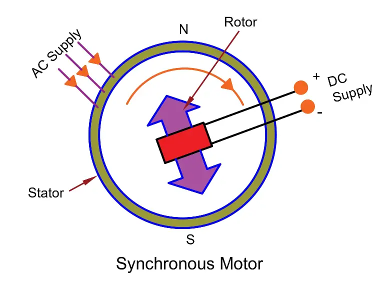
Working Principle of Synchronous Motor
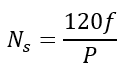
A synchronous motor is a doubly-excited machine where different power sources supply the stator and the rotor. A three-phase alternating current source supplies the stator windings, whereas the rotor field winding is excited by a DC source. This is done to achieve the magnetic locking between the stator and the rotor so that the rotor can rotate at the synchronous speed, which is the speed of the rotating magnetic field (RMF) generated in the air gap between the stator and the rotor. The synchronous speed depends on the supply frequency and the number of poles in the machine. It is given as
The stator windings are supplied by a three-phase AC supply, which causes a rotating magnetic field (RMF) to be generated in the air gap. This causes the generation of alternating poles on the stator. The rotor is supplied by a DC source, which causes the generation of fixed poles on the rotor windings. As we know, opposite magnetic poles attract each other while the like poles repel. This principle is put to use in the case of a synchronous motor. As soon as the rotor magnetic poles align with the opposite magnetic poles on the stator armature windings, the rotor gets attracted and begins to rotate at a synchronous speed. Once the alignment is done, the DC supply to the rotor field winding is cut off.
If the rotor aligns and rotates at the same speed as the rotating magnetic field, no load torque is generated, and the rotor position could be considered its equilibrium position. However, when the motor is loaded, the rotor begins to fall behind that position. It is then attracted by the opposite stator magnetic poles, which causes the generation of load torque by the rotor, and it accelerates. However, the rotor overshoots its equilibrium position and moves ahead of its intended position. It is again attracted back by the stator poles, but this causes it to de-accelerate and fall behind. This phenomenon, where the rotor oscillates about its equilibrium position depending on the load, keeps on going for a while, and it is known as ‘hunting.’
As the load is increased, the angle between the rotating magnetic field and the rotor also keeps on increasing as the rotor undergoes hunting. At an angle of 90 degrees between the rotating magnetic field and the rotor, the rotor generates the maximum torque possible. If this angle goes beyond 90 degrees, the rotor fails to generate load torque and stalls.
Characteristic Features Of A Synchronous Motor
- A synchronous motor will only run at synchronous speed.
- The speed of the motor can be changed by changing its supply frequency.
- Synchronous motors are not self-starting. Synchronous motors require an external force to near synchronous speed and need some external force to bring them near the synchronous speed.
- Synchronous motors can operate under both lagging and leading power factors, making them ideal for power factor improvement.
Applications of a Synchronous Motor
- Constant speed applications
- Power factor correction: A synchronous motor can operate with either a leading or lagging power factor, making it suitable for improving the power factor. When static capacitors cannot be used, a synchronous motor with a leading power factor can be connected to a power network under no-load conditions.
- Voltage regulation
- To change the frequency in an alternator
- For precise positioning in robotics
- In general, applications like grinders, pulp beaters, rock crushers, ball mills, steel mills, metal rolling mills, cement mills, rubber and textile mills, centrifugal pumps, air compressors, fans, blowers, line shafts, turn tables, timers, clocks, juicers, tape recorders and players, mixtures, signaling devices, indicating, regulating and controlling devices.
Related Articles: