This article describes the concept of sag in transmission lines, its importance, and step-by-step methods for accurately calculating sag to ensure efficient and safe power transmission.
What is Sag in a Transmission Line?
Sag in a transmission line is the vertical difference in level between the conductor support points and the lowest point of the conductor.
Overhead conductors transmit power from the power station to the distribution end and from the distribution end to the consumers. Hence, they are one of the critical infrastructures in the power system.
Transmission towers support the overhead conductors on two ends. The conductors aren’t stretched between the supports but hang between them with a slight curvature around their midpoint. The vertical distance between the support points (which are parallel and equal) and this point of curvature is known as sag.
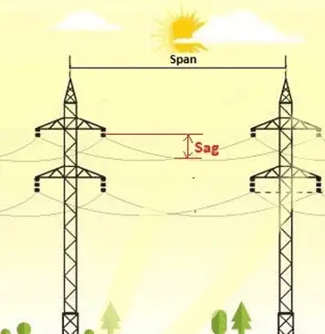
The picture above shows the sag of an overhead conductor.
The picture also shows something known as span. It is the distance between the parallel conductor-support structures or the transmission towers. Span is of two types.
- Equal or Level span: When both support structures are at the same base level and of the same height, they are said to have an equal span.
- Unequal span: When both support structures aren’t on the same base level (like in a hill slope) or at the same height or both, it is called an unequal span.
Importance of Sag in a Transmission Line
The picture below denotes sag in an overhead conductor.
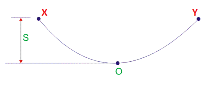
Here, ‘S’ denotes sag, which is the distance between the support points (X and Y) and the curve point ‘O’.
Sag is an important feature of an overhead line. This is because the transmission line can’t be stretched to its limits between the support points as it experiences varying physical conditions like wind, rain, snowfall, heat from the sun, etc. If the overhead line remains stretched and tense, it may break down and cause related problems.
That’s why the overhead lines are provided with a certain curve at a point between the two support points, which is termed sag. However, too much sag is also undesirable as it may decrease the distance between the ground and the conductor, thus causing a potential threat to the nearby locations.
Thus, it is important to have a nominal value of sag that can be derived mathematically.
Calculating Sag in a Transmission Line
Before we go for the sag calculation, certain points need to be noted.
- When the overhead conductor is supported on two ends at equal spans, a curve is formed at a point almost at the midpoint of the conductor. This is known as sag, which is much smaller than the span.
- The tension in the conductor at each point acts tangentially.
- The sag span curve is parabolic.
- The tension at support is almost equal throughout the conductor.
- The horizontal component of this tension is almost constant throughout the conductor
There are two different conditions for the calculation of sag
:a. Sag for equal span
b. Sag for an unequal span
Sag for Equal Span conductor in transmission line
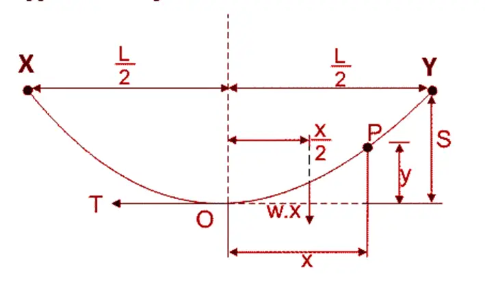
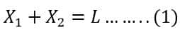
Let the span be ‘L’ between the two support points denoted by X and Y, respectively. ‘T’ denotes the tension in the conductor acting tangentially to the conductor.
w’ is the weight per unit length of the conductor.
We assume any point on the conductor, say ‘P.’ The vertical distance of this point from O is denoted by y, where ‘O’ is the lowest point of the conductor.
‘S’ is the sag, the vertical distance from support points to O.
‘x’ is the horizontal distance between points O and P.
Under balanced conditions, the two moments of force about point O remain equal. Therefore, we can equate both as
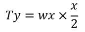
Putting,
![]()
and,

We get;
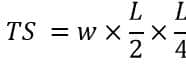
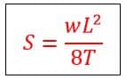
Therefore, The formula of sag for an equal-span overhead conductor is as follows;
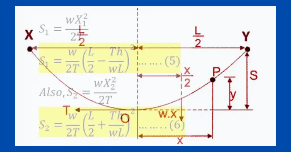
Sag for Unequal Span conductor in transmission line
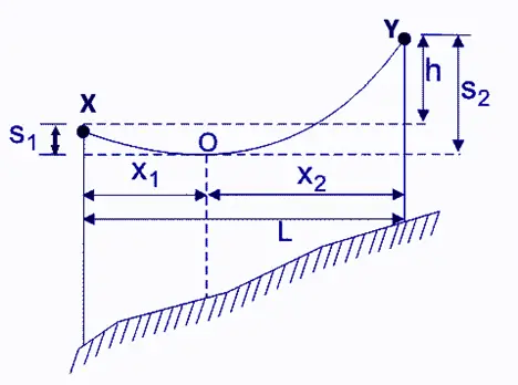
The above picture represents the situation of unequal support levels. In this case, there are two types of sags – one for each of the support levels shown by X and Y. Both the support levels are not on the same base or at the same height.
Here,
L is the span of the conductor
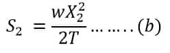
S1 and S2 = Two sags each from two support levels, X and Y.
AB is the conductor terminal, with O being the lowest point between them.
X1 = Horizontal Distance of point O from the lower-level point X.
X2 = Horizontal Distance of point O from the upper-level point Y.
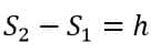
h = Difference in height of both levels.
T is the tension of the conductor acting tangentially, and w is the weight of the conductor per unit length.
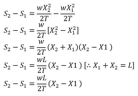
Therefore, both the sags S1 and S2 can be given as
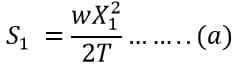
And,
From the diagram, we can say,
And,
Again, from the diagram, we can say that
Therefore,
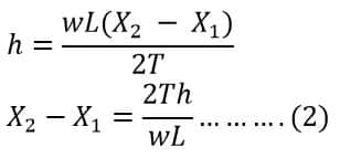
Solving both equations (i) and (ii), we get
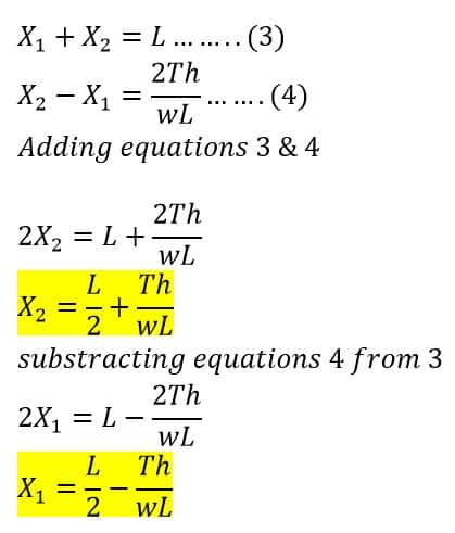
Therefore, by knowing the conductor span (L), Tension in the conductor (T), and the difference in the heights of both the levels (h) and weight of the conductor per unit length (w), we can calculate X1 and X2. Thus, by putting the values of X1 and X2 in equations (a) and (b), we can get the value of both the sags S1 and S2.
So,
Putting the value of X1 in equation(1) we get;
It should be noted that the weight per unit length of the conductor taken here is its own length, assuming the normal conditions of temperature, wind speed, and other physical conditions. However, the sag in an overhead conductor is also affected by snow (during snowfall) and wind (during strong winds).
Effect of Snow and Wind on Sag
- The effective weight per unit length of the conductor changes due to wind or the accumulation of ice during snowfall.
- Wind flow affects the conductor weight per unit length in the horizontal direction or along its direction of flow.
- Snowfall causes an accumulation of ice on the conductor, which tends to increase the conductor weight per unit length vertically downward or in the direction of the snowfall.
- When snowfall and wind flow are simultaneous, a resultant force is applied to the overhead conductor at a certain angle whose horizontal component is along the direction of the wind’s flow and the vertical component is along the direction of the snowfall.
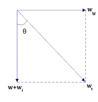
The picture above shows the combined effect of snowfall and wind on the conductor.
Here
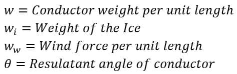
Therefore,
And,
So, we need to calculate ww and wi.
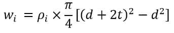
Calculation of wi
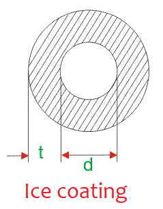
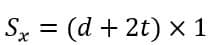
The picture above represents the overhead conductor coated with ice where d is the diameter of the conductor and ‘t’ is the thickness of the ice sheet.
Therefore,
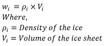
Therefore,
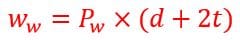
Calculation of ww
Similarly, the wind force per unit length of the conductor can be calculated as
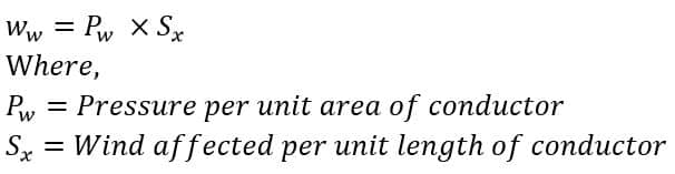
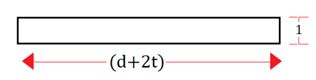
We assume that the conductor is stretched along its effective diameter (that is with ice sheet included) due to the wind such that it forms a rectangle whose length is equal to the diameter of the conductor and has unit width.
Therefore,
Therefore,
Thus, we can calculate the value of both wi and ww and get the value of the resultant force wt and the resultant angle θ using the equations that we derived at the beginning.
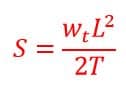
Therefore, the effective sag in such a conductor is given as
Advantage of Sag
Sag in the conductor ensures its durability during extreme weather conditions. It reduces the tension within the conductor, which may cause it to snap off its support point. It also helps reduce stress on the towers’ supporting mounts.
Disadvantage of Sag
While sag is important, too much sag may reduce the effective distance between the conductor and the earth, thus defeating the entire purpose of laying down conductors overhead. In addition, sag increases the conductor’s weight, and the overhang conductor (the amount of conductor only required to create sag) raises the initial cost.
It is quite a useful material for an Electrical Engineer