The spool type of directional control valve is the most common type of valve used in industrial hydraulic systems. A cylindrical shaped spool made of metal (stainless steel, or aluminum). It is located in the metal body housing. The valve housing is cut with different ports and the spool element can only move axially (sometimes rotational).
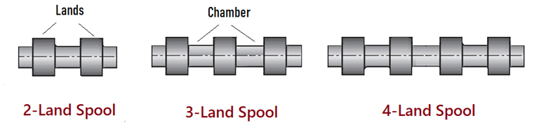
Spool comprises raised body called lands, and a chamber portion. The flow paths in the housing are opened and closed by moving the spool between passages, allowing fluid to flow from or to the work ports. Fluid enters the chamber and moves the spool with a certain force.
The manufacture of the spool valve is simple and cheap. Two types of spools are
- Rotary spool valve
- Sliding spool valve
The spool can be operated mechanically by wheels, cams, and rollers. Manually by levers. Electrically by solenoid. Hydraulic or pneumatic by fluid pressures.
Rotary Spool Valve
Rotary spool valves are generally operated manually. Four-way directional control valves of the rotary spool valves are often used as pilot valves to direct flow to and from other valves as shown in the figure below. Fluid is directed from one supply source through the rotary valve to another directional control valve. This valve positions the valve to direct flow from another source to one side of a drive unit.
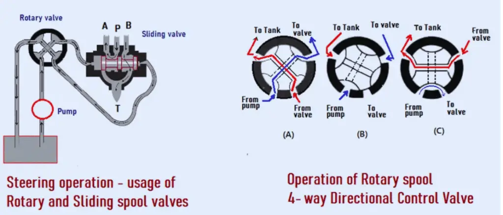
Fluid from the other end of the main valve goes through a return line, through the alternative valve to the return (if hydraulic) or exhaust (if pneumatic) port. The main parts of a spool rotary directional control valve are shown in the above figure. The figure shows the operation of rotary as well as sliding spool valves.
View-A and C show the valve in a position to deliver fluid to another valve, while view B shows the valve in the neutral position, with all passages through the valve block.
Sliding Spool Valve
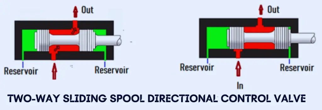
The sliding spool two-way directional control valve is operationally similar to the three, four-way valve. The sliding spool valve is so named because of the shape of the valve element. In the housing, it slides back and forth to cover and uncovers the ports. The sliding element is also referred to as a piston or spool.
The directional control valve consists of a valve block containing four fluid ports.
- Pressure (P)
- Return to tank (T) /exhaust
- Two-cylinder ports (A and B).
A sleeve is located in the main bore of the block. O-rings made of Teflon material are placed at intervals around the outside diameter of the sleeve. These rings form a seal between the spool and the body. It creates watertight compartments around the sleeve. Each of the compartments aligns with one of the fluid ports in the body.
The sleeves have a pattern of holes drilled through them to allow fluid to travel from one port to another. A series of holes are drilled in the hollow center sleeve in each compartment.
Sliding spool valves operate in four configurations
- Open-center condition
- Float center condition
- Closed center condition
- Tandem center condition
Open-Center Valve Condition
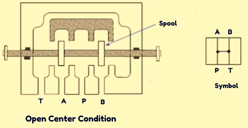
The open-center condition is shown by the symbol with all four ports connected.
The figure shows that ports A, B, P, and T are interconnected in an open-center configuration. In this condition, the actuator is not held under pressure and the pump flow proceeds to the tank at low pressure. This spool helps minimize shock when moving from one position to another.
Applications
- Rotary actuators can be controlled in either direction by open-center spool valves.
- This type of center condition is used when pump flow is supposed to perform a single operation only.
- An application, where the actuator is not held under pressure, is suitable for this condition.
Float Center Valve Condition
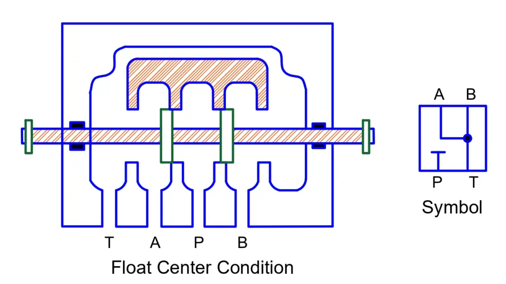
In the float center condition, the pressure port is blocked and the actuator ports are connected to the tank ports as shown in the figure. The symbol of a float center condition shows the actuator port A and B connected to the tank.
It is in this condition, pressure is maintained in the pressure port and removed from the actuator port to the tank. In the symbol of a float center condition, actuator ports A and B are connected to tank port T and pressure port P is blocked.
Application
In pilot-operated directional valve applications, this center condition is used.
Closed Center Valve Condition
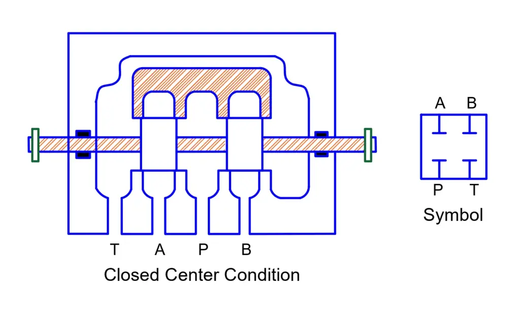
As shown in the figure above, all ports are blocked in the closed center condition. This condition prevents the fluid from passing through the valve and allows for any other operation to be performed. The symbol for closed center condition shows all four ports blocked.
The disadvantage of the closed center condition is that the pump flow cannot go to the tank under this condition and there is a possibility of leakage.
Application
The valves with the closed center condition are used when a single pump performs more than one operation and where there must be no pressure loss.
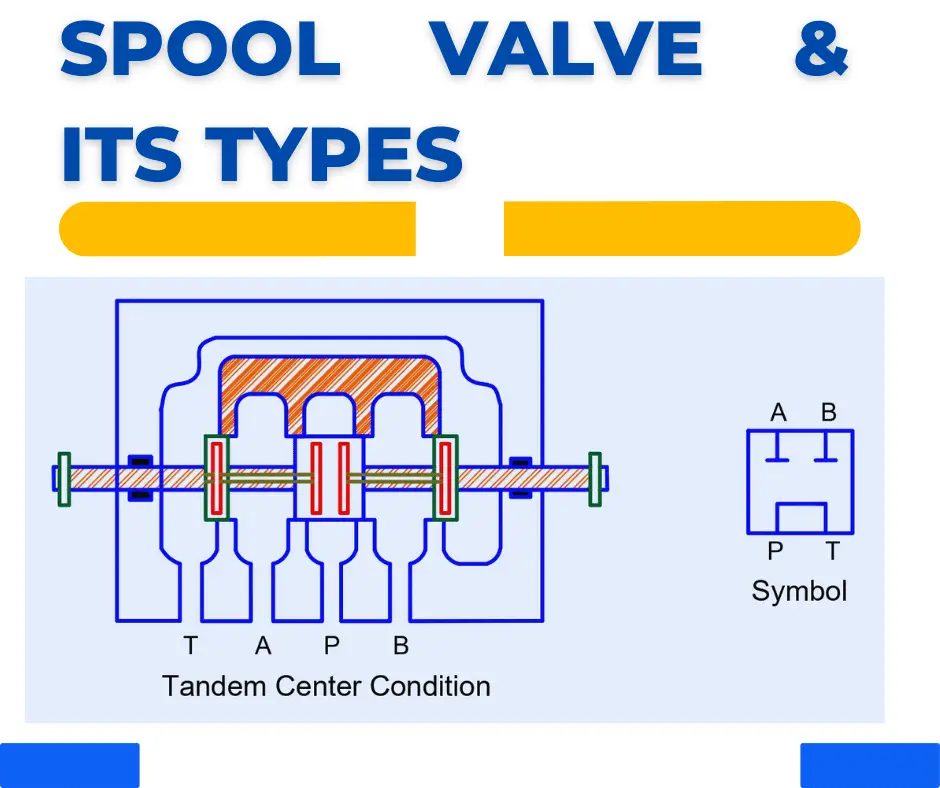
Tandem Valve
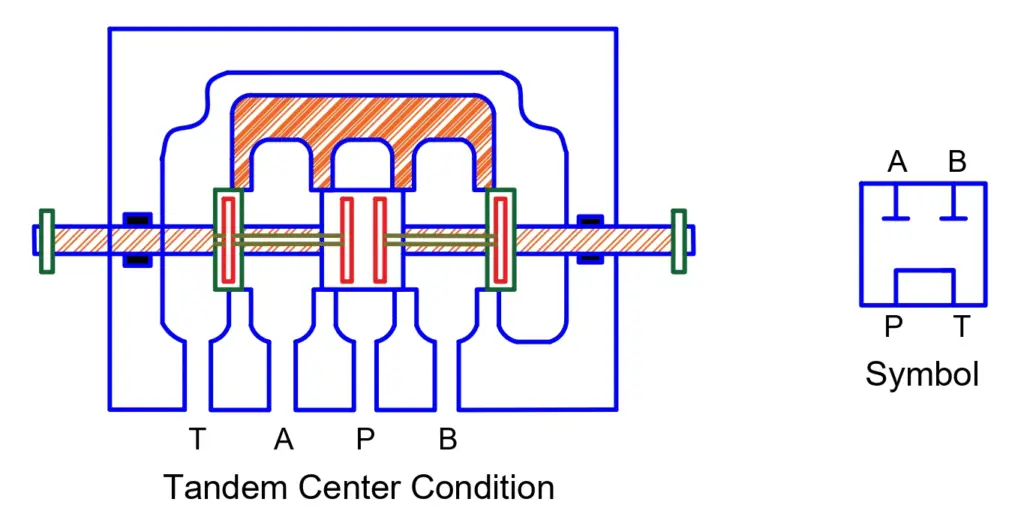
In the tandem center condition, the pressure port is connected to the tank port and both the actuator ports are blocked as shown in the figure above. Under this condition, the flow of the pump is delivered to the tank at low pressure. The symbol of a tandem center condition shows actuator ports A and B blocked and pressure port P connected to tank port T.
Application
The tandem center condition configuration is used in applications where two or more actuators are connected in series with the same power source.