An electrical Tachometer is an electromechanical device that produces an output voltage proportional to the speed. In this article, we will discuss the AC tachometer and DC tachometer and their advantages and disadvantages. Let us start with the basic definition of an electrical tachometer.
What is an Electrical Tachometer?
The device which is used to measure the rotational speed or angular velocity of a machine like a motor or a generator is called an electrical tachometer.
The operation of an electrical tachometer is based on the principle of relative motion between the shaft and magnetic field of the electrical machine. The relative motion between the magnetic field and the shaft induces an EMF in a coil that is placed in the constant magnetic field produced by a permanent magnet. This induced emf is directly proportional to the speed of rotation of the shaft of the machine.
Basically, there are two types of tachometers, i.e. mechanical tachometer and electrical tachometer. A mechanical tachometer is one that measures the rotational speed of the machine shaft in RPM (Revolutions per Minute). On the other hand, the electrical tachometer measures the speed of rotation of the machine shaft in terms of electrical voltage or emf. There are several advantages of electrical tachometers over mechanical tachometers making electrical tachometers popular.
Types of Electrical Tachometers
Electrical tachometers are further classified into the following two types based on the nature of induced emf, i.e.
- DC Tachometers
- AC Tachometers
Let us now discuss each type of electrical tachometer in more detail.
What is DC Tachometer?
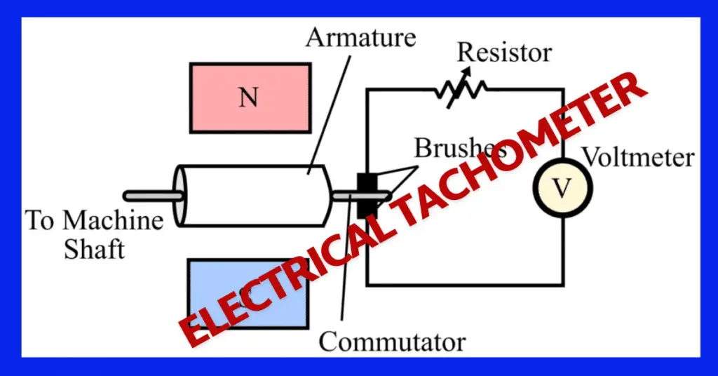
The construction diagram of a DC tachometer is shown in figure-1.
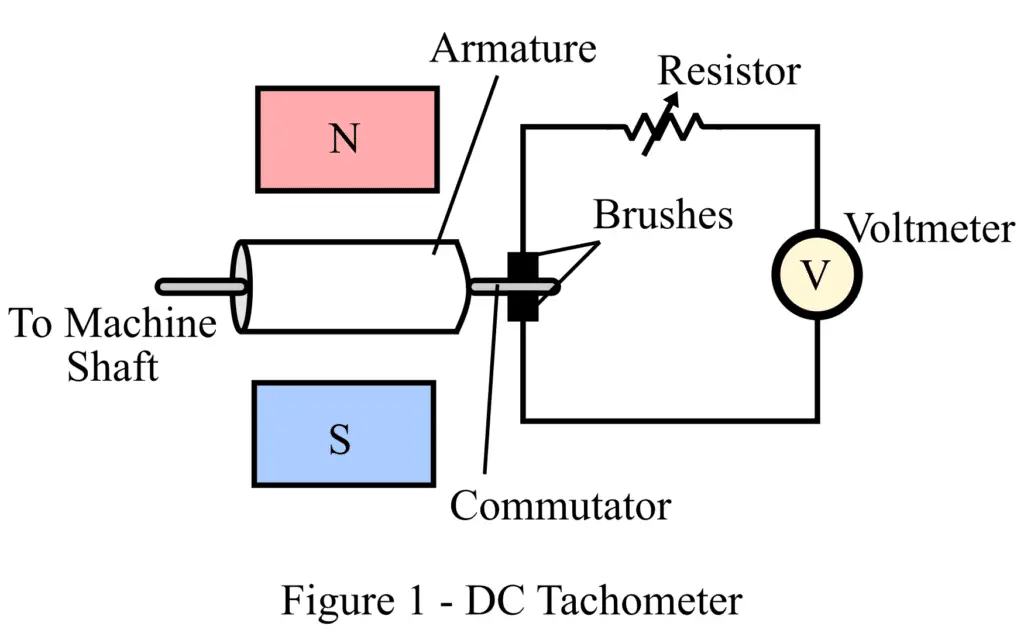
The main parts of a DC tachometer include a permanent magnet, armature coil, commutator and brushes, a variable resistor, and a moving coil voltmeter. Thus, it is similar to a DC generator in construction, for this reason, it is sometimes also called a DC Tachometer Generator.
The shaft of the DC tachometer generator is coupled to the shaft of the machine whose speed is to be measured.
The working principle of a DC tachometer is simply the electromagnetic induction principle, i.e. when a closed conductor coil is moved in a magnetic field, an emf is induced in the coil. The magnitude of this induced emf is the function of flux linkage to the coil and rotational speed of the shaft.
This induced emf in the armature of the DC tachometer is alternating in nature. Hence, using a commutator and brushes, it is converted into direct voltage to measure with the voltmeter. Also, the polarity of induced emf provides information about the direction of rotation of the shaft. The variable resistor is used in the circuit to control the heavy current flow in the circuit.
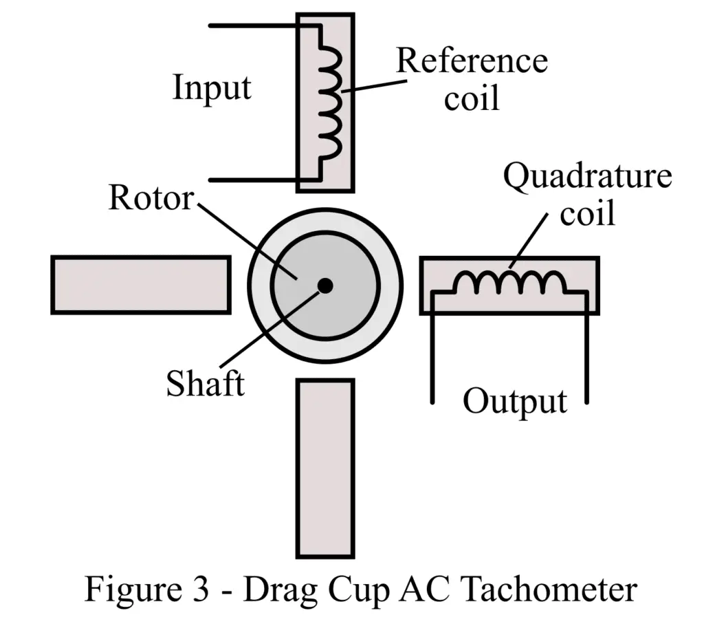
The expression of induced emf in the armature of the DC tachometer is given by,
Where E is the induced emf, ϕ is the flux per pole, P is the number of poles, N is the speed of rotation, Z is the number of conductors in the armature, and A is the number of parallel paths in the armature coil.
From this equation, it is clear that,

DC tachometer has several advantages and disadvantages which are given below.
Advantages of DC Tachometer
The important advantages of a DC tachometer are as follows:
- We can use the traditional DC voltmeter to measure the induced emf.
- The generated output voltage is directly proportional to speed.
- The direction of rotation can be determined by knowing the induced emf’s polarity.
- The DC tachometer produces about 10mV/rpm and we can measure the generated voltage by a moving coil voltmeter having a uniform scale.
- The series resistor in the tachometer limits the current in the condition of a short circuit at output terminals.
Disadvantages of DC Tachometer
The major disadvantages of DC tachometer are as follows:
- It requires frequent maintenance due to the presence of a commutator and brushes. The error in measurement can creep if there is a change in the contact resistance between the brushes and the commutator.
- It has high output resistance compared to the input resistance, and if a high current flows through the armature coil, it can distort the magnetic field of the permanent magnet.
What is AC Tachometer Generator?
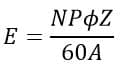
The construction of an AC tachometer generator is shown in figure-2.
The drawbacks associated with the DC tachometer are eliminated in the AC tachometer. As can be seen that it consists of a static armature and a rotating magnetic field system. Hence, there is no need for a commutator and brushes in the AC tachometer.
The rotating magnetic field induces an emf in the armature coil according to the principle of electromagnetic induction. Here, the magnitude and frequency of the induced emf are directly proportional to the speed of rotation of the shaft. when the measurement of the induced voltage procedure is adopted, the output voltage of the tachometer is rectified to get the DC voltage.
A rectifier circuit is used to rectify the AC voltage into DC and the capacitor smoothens the DC by eliminating ripples in the DC voltage. The output of the rectified AC voltage is measured by a moving coil voltmeter. The reading of the voltmeter shows the speed of the rotation.
Advantages of AC Tachometer
- The frequency and amplitude of induced voltage in the stator are proportional to speed. of the rotation of the machine.
- It is possible to measure the speed in two ways, by measuring the frequency or by measuring the magnitude of v the induced voltage.
- The AC tachometer does not have problems caused by the commutator because the AC generator does not have a commutator and carbon brushes.
- We can measure the rectified output voltage with a moving coil voltmeter.
- The speed and output-induced EMF and frequency have a linear relationship.
Disadvantages of AC Tachometer
- The output frequency and voltage are very low under low-speed conditions.
- The frequency increase with an increase in the speed of the tachometer. The impedance of a coil is frequency dependent. Therefore, the impedance of the coil increase under high-speed conditions. The input impedance of the display device or measuring instrument must be high compared to the coil’s impedance in order to have good linearity.
Drag Cup Rotor AC Generator
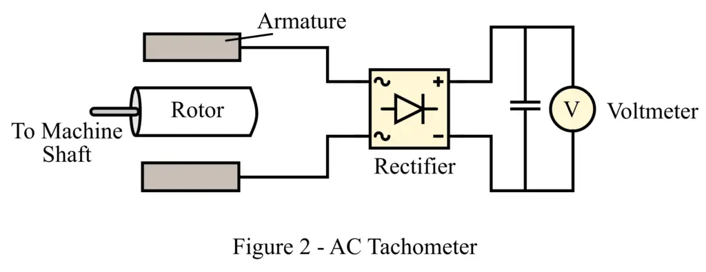
The AC tachometer is also constructed in another construction named, Drag Cup Type AC Tachometer. The construction of a drag cup-type ac tachometer is shown in figure-3.
In this type of AC tachometer, the stator carries two windings namely, reference winding and quadrature winding. Both windings are displaced by 90° from each other. The rotor of the drag cup tachometer is made up of a thin aluminum cup and is placed within the stator. The cup is named a drag cup because it is directly connected to the object whose speed is to be measured.
The rotor has very low inertia and high inductance. In this tachometer, the AC supply is input to the reference winding, and the output is taken from the quadrature winding. The rotating rotor in the magnetic field induces an emf in a sensing winding which is proportional to the rotational speed.
A reference AC voltage Vr cos ωct is applied to the reference coil whose resistance and reactance are negligible. The coil produces magnetic flux Φr sin ωct that lags the reference voltage by 90° and sets up a magnetic field in the air gap.
When the drag cup rotates in the air gap of this magnetic field an emf is induced in the cup and a current flows through it. Due to this induced emf, a quadrature flux Φq is produced which in turn leads to a transformer action, and an emf eq is induced in the quadrature coil.
Advantages of Drag Cup Type Tachometer Generator
- It produces a ripple-free output voltage, hence no need for a filter.
- The phase detector can determine the direction of rotation by measuring the phase of its output voltage of the drag cup tachometer.
- It is less relatively expensive.
- When high speed is measured with this tachometer, a large error in measurement happens because of non-linearity in output voltage with respect to the input(speed).
- The nonlinearity in the measurement occurs when it is used for measuring high speed. It is possible to reduce the error on account of non-linearity by selecting an excitation voltage frequency much higher than the frequency of the speed signal. The carrier frequency must be 5-10 times higher than the speed signal frequency.
- They are robust in construction and need less maintenance.
Disadvantages of Drag Cup Type Tachometer
The followings are the disadvantages of a drag cup tachometer.
- At high speeds, the output voltage is not linearly increase with the speed. For making the output linear, the reference winding is excited with above 400 Hz frequency.
- The calibration of the drag cup tachometer is comparatively complicated because it requires two signals-reference signal and a speed signal. The reference signal must be constant for the calibration of the tachometer.
This is all about Electrical Tachometer: DC Tachometer and AC Tachometer.
Read Next: