Schering bridge is a type of AC (alternating current) bridge used to measure different parameters of a capacitor such as capacitance, dielectric loss, and power factor. The Schering bridge is one the most popular bridges that are used to measure unknown capacitance.
Since, the Schering bridge is a type of AC bridge, hence it also works on the same principle as the other ac bridges do. In other words, it works on the principle of bridge balance, i.e. the unknown capacitance is determined by balancing the bridge and comparing the unknown value with standard values.
There are two circuit constructions of the Schering Bridge, which are:
- Low Voltage Schering Bridge
- High Voltage Schering Bridge
Now, let us discuss each of these two types of Schering bridges in detail one by one.
Low Voltage Schering Bridge
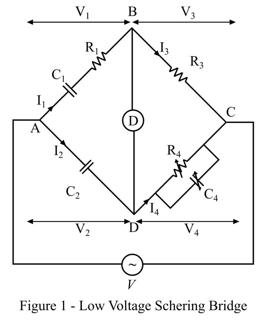
The circuit construction of the low-voltage Schering bridge is shown in Figure 1. Like any other ac bridge, this bridge also consists of four arms namely AB, AD, BC, and CD. Where arm AB has a capacitor C1 whose capacitance is to be measured and a resistor of resistance R1. The resistance R1 represents the dielectric loss of the capacitor C1. The arm AD has a standard capacitor C2. The arm BC has a non-inductive standard resistor R3, and the arm CD consists of a variable capacitor C4 and a variable non-inductive resistor R4, which are connected in parallel with each other. An AC voltage source is connected across terminals A and C of the bridge circuit.
Since the Schering bridge is based on the principle of null deflection, hence to detect the balance condition of the bridge a null detector is used which is connected between terminals B and D as shown in figure-1.
Now, let us derive the expression of the unknown capacitance for the given bridge circuit.
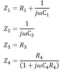
From the bridge circuit shown in figure-1, the impedances of its branches are,
When the bridge is in the balance condition, we have,
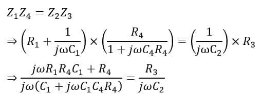
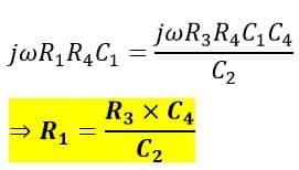
On arranging the equation, we get,
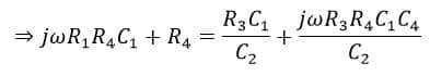
Now, on equating the real terms of this equation, we get,
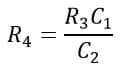
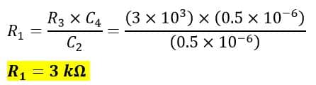
Thus, the value of unknown capacitance C1 is,
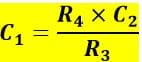
And, on equating the imaginary parts of the equation, we get,
Hence, we can use these two equations to calculate the value of unknown capacitance and the dielectric loss in the capacitor R1.
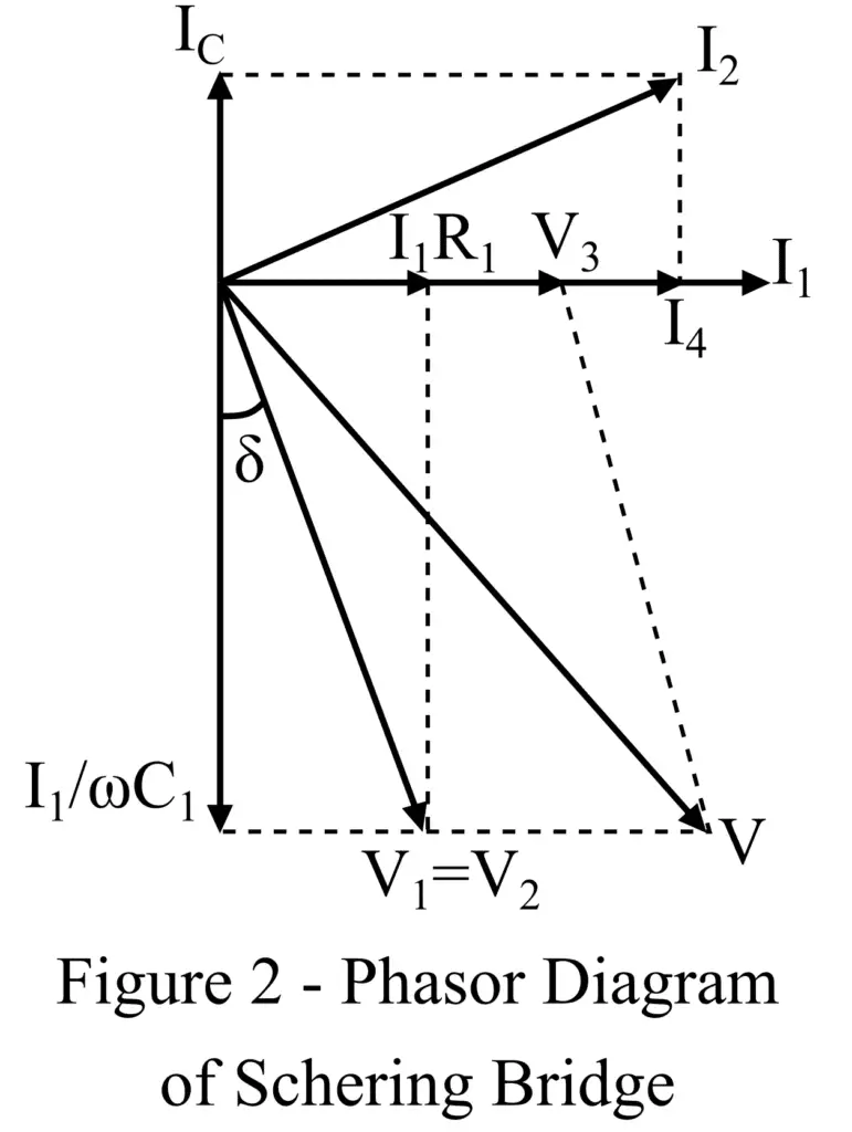
The phasor diagram of the low voltage Schering bridge is shown in Figure 2.
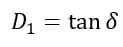
We can also determine the dissipation factor of the unknown capacitor as follows:
From the phasor diagram, we have,
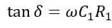
On substituting the values of C1 and R1, we get,
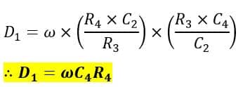
This is the dissipation factor of the capacitor under measurement.
Limitations of Low-Voltage Schering Bridge
The following are the major limitations of the low-voltage Schering bridge:
- The null detector used in the bridge is not very sensitive.
- In the low-voltage Schering bridge, it is slightly difficult to obtain the balance condition of the bridge.
- There are some errors present in the measurement of small capacitances.
- The calibration of the bridge is to be done to determine the dissipation factor at different frequencies.
Now, let us discuss the second type of Schering bridge, i.e. high voltage Schering bridge.
High Voltage Schering Bridge
The high-voltage Schering bridge is mainly designed to measure small capacitances at high voltage and high-frequency values. This bridge circuit overcomes the limitations of the low-voltage Schering bridge.
The following are the major advantages that make the high-voltage Schering bridge a most suitable method for the measurement of capacitance at high voltages:
- The null detector (a vibration galvanometer) used in the high-voltage Schering bridge is highly sensitive.
- It gives very accurate results.
- Power loss due to resistance present in the circuit is very small.
- The use of Wagner’s earth device eliminates the errors due to earth capacitance.
The circuit construction of the high-voltage Schering bridge is shown in Figure 3.
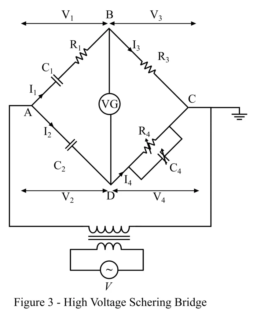
The circuit of this bridge consists of four arms namely, AB, AD, BC, and CD. Here, arm AB has a capacitor C1 in series with a resistance R1. The arm AD has a capacitance of C2. The arm BC has a capacitance of R3, and the arm CD has a variable capacitor C4 in parallel with a variable resistance of R4. A vibration galvanometer is connected between terminals B and D of the bridge.
The capacitors C1 and C2 used in this bridge are specially designed to work properly at high voltages. Also, these capacitors show very high impedances at the normal values of the supply frequency. Therefore, due to high impedance, the currents flowing in the arms of the bridge is very low, which results in low power consumption. Consequently, we can use a sensitive null detector in the bridge circuit.
Another important feature of this bridge is that its terminal C is connected to the ground which ensures the safety of the bridge’s operator. Also, in the high voltage Schering bridge, the spark gaps are provided at each arm of the bridge to prevent the dangerous high voltage that appears across the arms BC and DC due to the breakdown of the high voltage capacitors.
Precautions to Ensure High Accuracy
The following major precautions are to be taken to ensure high accuracy in the measurement of the capacitance:
- In the high voltage Schering bridge, the wanger’s earth device must be provided to eliminate the effect of earth capacitance on the detector.
- Earth screens must be used in the bridge circuit to eliminate errors in measurement due to internal capacitance between high-voltage and low-voltage arms.
- A guard ring is to be used to eliminate the error due to dielectric loss in capacitor C2.
Advantages of Schering Bridge
The following are the major advantages of the Schering bridge:
- The Schering is relatively less expensive as compared to other ac bridges.
- Its balance equation is independent of the frequency.
- Schering bridge can measure the insulating properties of electric cables and devices.
- Using the Schering bridge, we can measure the dissipation factor of the capacitor.
Hence, this is all about the low-voltage Schering bridge and high voltage Schering bridge. Now, let us discuss a solved numerical example to understand the calculation of the capacitance using the Schering bridge formula.
Numerical Example on Schering Bridge
A Schering bridge has the following circuit parameters:
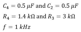
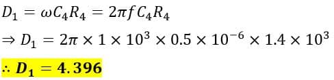
Determine, the value of C1 and R1, and the dissipation factor D1.
Solution
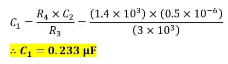
The values of C1 and R1 are given by,
The dissipation factor of the capacitor is,