Desauty’s Bridge & Modified Desauty’s Bridge. are used to find the value of unknown capacitance. They are also used to compare the value of two capacitances.
Desauty’s bridge is a type of AC (Alternating Current) bridge that is employed for the measurement of unknown capacitance. The major advantage of Desauty’s bridge is that it gives a high degree of accuracy in the measurement of capacitance over a wide range of capacitances. Also, we may utilize De Sauty’s Bridge to compare two capacitances.
There are two circuit construction of Desauty’s Bridge, namely-
- De Sauty’s Bridge
- Modified De Sauty’s Bridge
Let us discuss each of these two bridges one by one.
Desauty’s Bridge
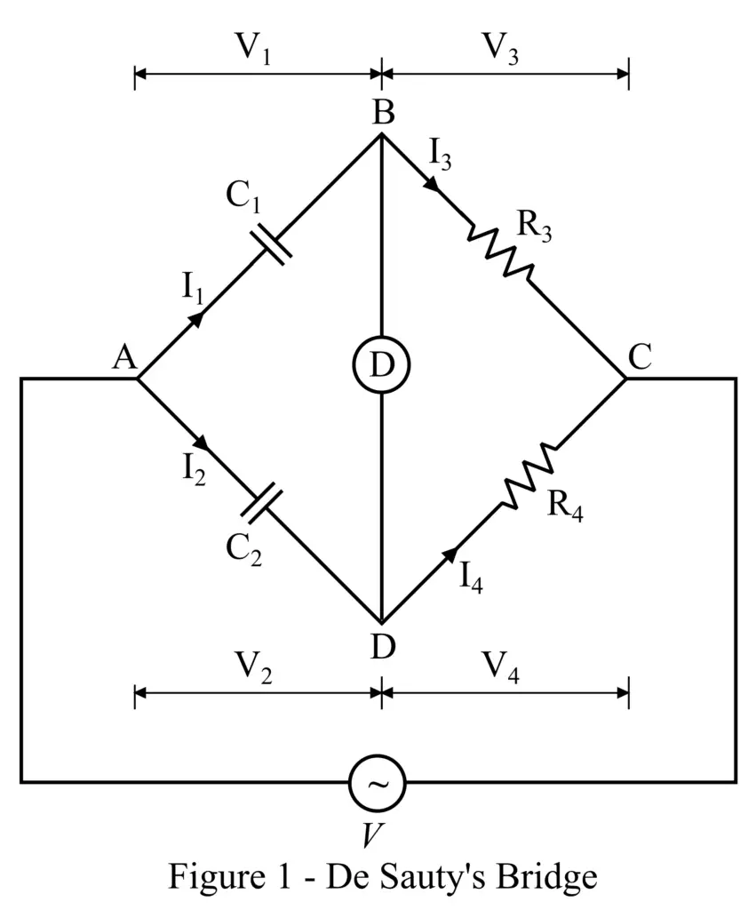
The circuit construction of De Sauty’s bridge is shown in Figure 1. It consists of four arms. Where, arm AB has a capacitor, whose capacitance C1 is to be determined. The arm AD has a known standard capacitor of capacitance C2. The arms BC and CD have two standard non-inductive resistors whose resistances are R3 and R4 respectively. A source of AC voltage is connected across terminals A and C.
Desauty’s bridge is based on the principle of null deflection, i.e. its balance condition is denoted by the null deflection of the null deflection inductor, which is connected between terminals B and D as shown in figure1.
Now, let us derive the expression for the calculation of the value of the unknown capacitance.
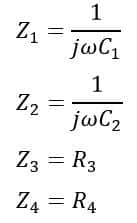
From circuit of the Desauty’s bridge, the impedance of each arm of the bridge is given as follows:
The bridge is said to be balanced if
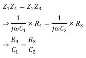
Hence, the value of the unknown capacitance can be determined by using the following formula,
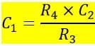
The most significant advantage of De Sauty’s bridge is its simple circuit construction and only variable component. Where we may select either resistor R3 or R4 as a variable component to bring the bridge into balance condition. The phasor diagram of Desauty’s bridge is shown in Figure 2.
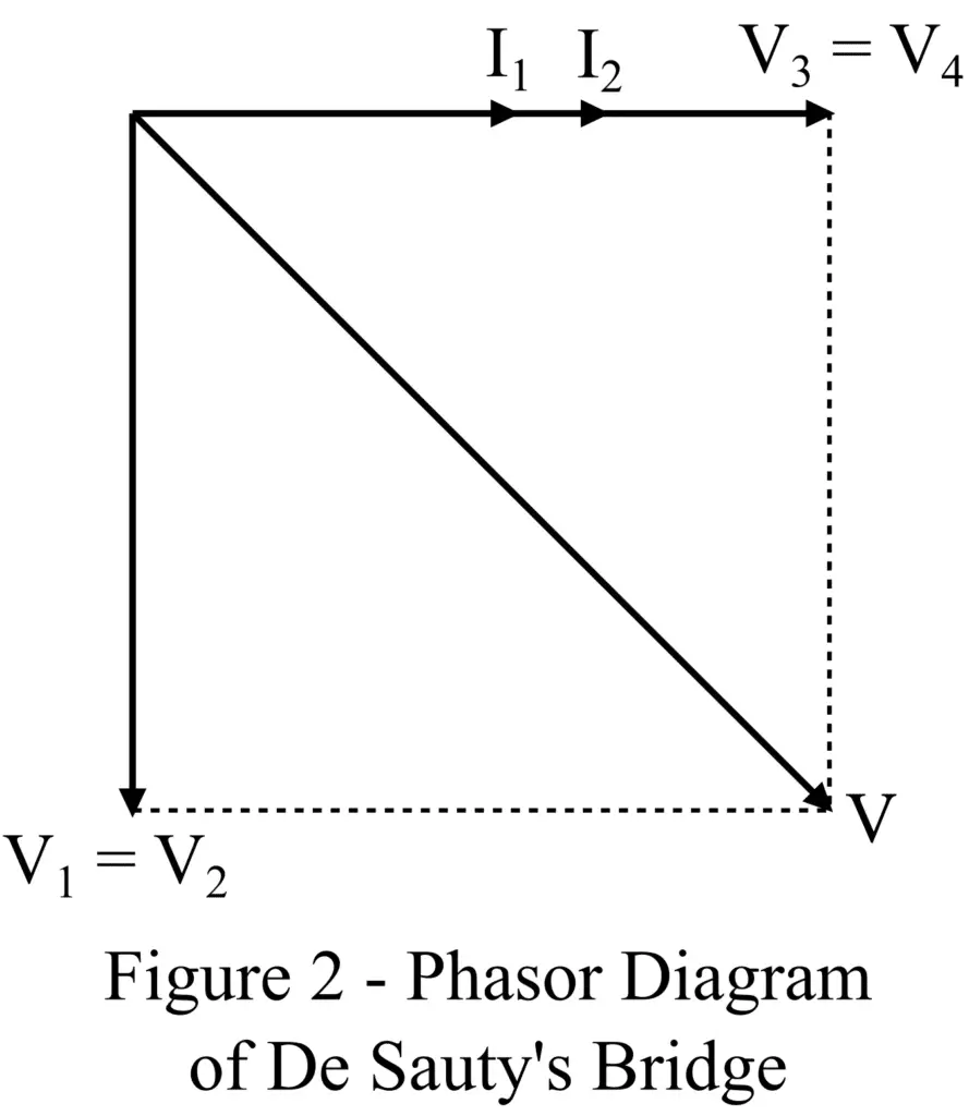
Now, let us discuss the modified De Sauty’s bridge, its circuit construction, and the phasor diagram.
Modified Desauty’s Bridge
The modified Desauty’s bridge is an enhanced version of the basic Desauty’s bridge. It is designed to measure the unknown capacitance of an imperfect capacitor. Where, an imperfect capacitor, also called a lossy capacitor, is one which has a finite internal resistance due to dielectric losses.
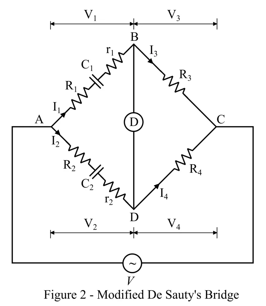
The circuit construction of the modified Desauty’s bridge is shown in Figure 3. The modified Desauty’s bridge consists of four arms namely, AB, AD, BC, and CD. The arm AB has a resistor R1 connected in series with an imperfect unknown capacitor whose capacitance is C1 and internal resistance is r1. The arm AD has a resistor R2 connected in series with an imperfect capacitor whose capacitance is C2 and internal resistance is r2. The arms BC and CD have non-inductive resistors whose resistances are R3 and R4 respectively.
Now, let us derive the expression for the calculation of the unknown capacitance of the capacitor C1.
From the circuit diagram of the modified Desauty’s bridge, the impedances of the arms of the bridge are,
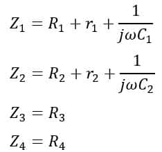
For the bridge to be in a balanced condition,
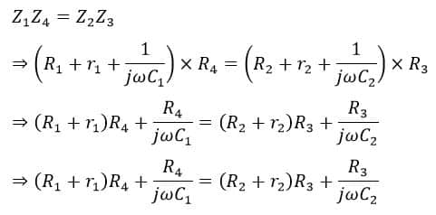
On equating real terms of the equation on both sides, we have,
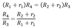
On equating imaginary terms on both sides, we have,
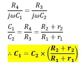
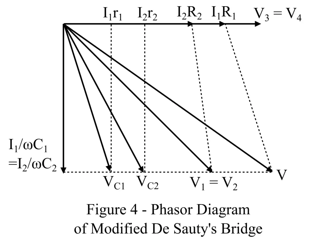
Hence, we can calculate the value of the unknown capacitance C1 using this formula. The phasor diagram of the modified De Sauty’s bridge is shown in Figure 4.
Thus, this is all about the construction and theory of Desauty’s bridge and Modified Desauty’s bridge. As we discussed, Desauty’s bridges are used to measure unknown capacitance in an AC circuit.