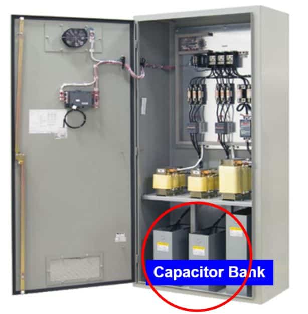
A capacitor bank is a group of several capacitors connected in the series or parallel combinations. Capacitors are electrical and electronic components that store electrical energy. Thus, capacitor banks (cap bank) stores the reactive energy (leading) and it compensate for reactive energy (lagging), and improves the power factor. As a result, the grid gets more stable and higher transmission capacity and suffers fewer transmission losses.
By incorporating a capacitor bank into the system, the power backlog can be corrected at the lowest cost to the business compared to making significant changes to the utility’s power grid or the system that is supplied.
To understand the importance of capacitor banks, let us discuss active, real, and apparent powers separately. Also the power factor.
The most common use of a capacitor bank is for AC power supply. Power factor correction is essential in industrial establishments that use a large number of transformers and electric motors. Because this equipment uses a large inductive load, they are susceptible to phase shifts and power factor lags in the power supply. It can cause a loss of system efficiency if not corrected.
Unity power factor
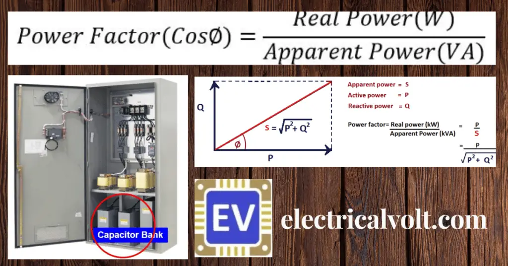
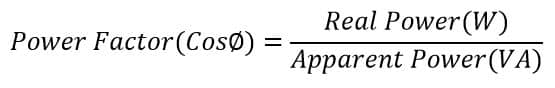
In AC circuits, the power factor is the ratio of real power used to do work to the apparent power supplied to the circuit. Power factor correction is an adjustment of the electrical circuit to bring the power factor as close to 1 as possible, known as the unity power factor.
Unity power factor refers to the case, where the current and voltage are in the same phase. Neither late nor early. The physical importance of the power factor is in the load impedance.
Inductive loads such as coils, motors, etc. have lagging power factor.
Capacitive loads for example capacitors have leading power factor, and resistive loads for example heaters have unity power factor.
Power factor close to unity
A power factor of one or unity power factor is the goal of any electric utility. If the power factor is less than one, they must supply more current to the user for a given amount of power consumption. And, it leads more transmission losses.
By doing so, they incur more power losses down the line. Moreover, there will be need of higher capacity equipment in place than would be necessary.
As a result, an industrial installation will be charged a fine if its power factor is very different from 1, depending on the electricity law of the country/state. The positive side of the maintaining good power factor is that the utility companies also pay incentive in the electricity bill if the power factor remains in the specified range for an entire month.
Important parameters
kVA: Total power or Apparent (S).
kW: Power to perform work, it is called active power (Q).
kVAR: Reactive power (S) is needed to generate a magnetic field in transformer motors.
For the correction of the power factor, only the demands of P (real power) and Q (reactive power) intervene, which are supplied to the load. After recording the data, the power factor is calculated from the ratio of the real power to reactive power. Power factor correction consists of reducing the reactive power demanded by the load so that kVA tends to be equal to kilowatts.
There is an energy saving that translates into economics, both by reducing the magnitude of the current that circulates through the electrical equipment. Also, by limiting the electrical losses caused by the heat loss(joule).
What is Active, Reactive, and Apparent power?
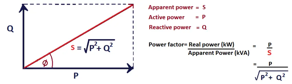
The best representation is a vector diagram, where the “Active” power is represented by the positive X-axis and the “Reactive” power by the Y-axis. The inductive power, that is, the one in charge of creating and maintaining an electromagnetic field around a coil, can be represented by the positive Y-axis.
Capacitive power can be represented on the negative Y-axis, therefore these two powers tend to cancel, resulting in a vector that can be positive or negative on the Y-axis.
Active power
“Active Power” is the power consumed by inductive loads that do real work either by creating heat, operating a load, etc. it is also called Real power.
Reactive power
“Reactive power” is power in which the current is out of phase with the voltage and the product of volts time amps (V*A) does no real work. In contrast to active power, reactive power cannot be transformed into work or heat. In simple terms, this reactive energy can be considered as phantom energy that circulates through the network but is not transformed or generates any benefit.
For example-the current that charges a capacitor or that creates a magnetic field around a coil.
Another simple way to explain this concept is using the following image:
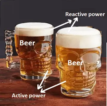
Foam in a beer glass does not satisfy the need for hydration, just like reactive energy. It takes up space, but it is not useful when generating any results or work.
Apparent power
“The Apparent power” is the mathematical combination of both real power and reactive power.
CosΦ is the power factor for a three-phase inductive motor in the order of 0.8 to 0.9. To reduce the angle Φ and improve the power factor, capacitors are added to the motor circuit. The function of these capacitors is to provide compensation against the magnetizing current and thereby reducing the amplitude of the reactive current in the mains.
Uses of Capacitor Banks
The followings are the uses of capacitor banks.
- Capacitor banks are equipment that is installed in electrical systems, both in low and medium and high voltage, since they are useful to correct the power factor and avoid the penalties that supplying company imposes, improve the profile of voltage, mainly during moor staring conditions or connection of large loads.
- When used as a part of harmonic filters, they help reduce the harmonic currents that circulate through the electrical network, avoiding electrical losses and equipment wear.
- Capacitor banks have been used to compensate for reactive power and voltage boost requirements in power systems.