The power triangle represents the active power, reactive power, and apparent power of the AC circuit in the right-angle triangle. The three sides of the right-angle triangle show the relationship between all three powers. A power triangle is a useful tool for calculating the power- active, reactive, and apparent power in an AC circuit if two out of three power is known. There are many combinations of electrical load like pure resistive, inductive capacitive, or combination of RL, RC, RLC, LC, etc. The inductive, and capacitive load draws reactive power from the source and feedback the power to the source again.
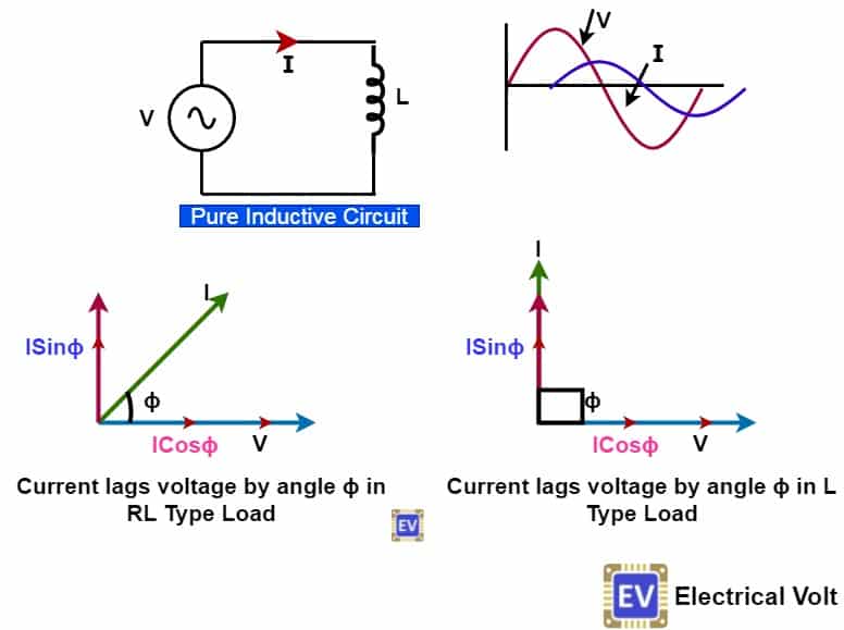
From the above phasor diagram, it is clear that inductive and capacitive circuits draw reactive currents. The total current in the circuit is thus the vector sum of active current and reactive current. We can show the active, reactive, and apparent power by a right-angle triangle.
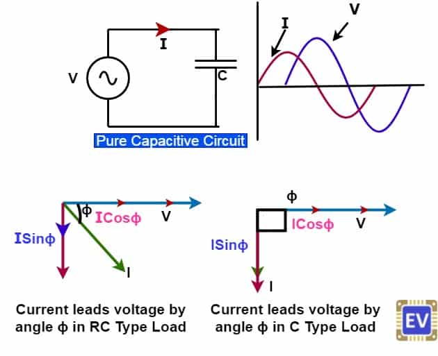
The reactive component draws a reactive current and its magnitude is ISinɸ. The active component draws active current, and its magnitude is I Cosɸ. The Product of the reactive component of current ( ISinɸ) and voltage(V) is the reactive power. The Product of the active component of current ( I Cosɸ), and voltage(V) is the active power. The resultant vector sum of the active and reactive power is the apparent power.
What is a Power Triangle?
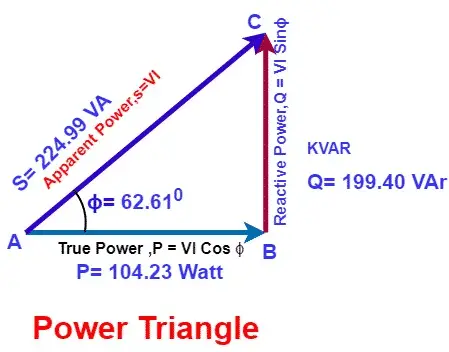
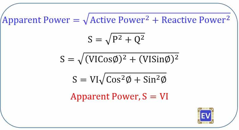
Hypotenuse = Apparent Power
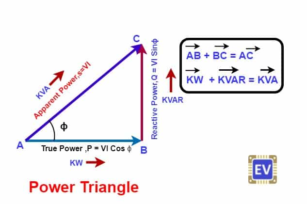
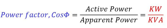
| Active Power (P) = VI Cosɸ [ Cosɸ = Power Factor ] |
| Reactive Power (Q) = VI Sinɸ |
| Apparent Power(S ) = VI* |
We can find the power of the AC circuit by power triangle if two out of three powers are available. Then, all three powers can be drawn on a power triangle to show the relationship between active power, reactive power, and apparent power.
Summary
-
We denote the active power on the base of the power triangle. The wattmeter measures the active power. Active power is the useful power used by the equipment to do useful work. The examples of the equipment drawing are electrical motor, oven, heater, geyser, etc.
-
The reactive power (inductive type) is used for electrical machines’ functioning. The induction motor draws inductive reactive power to produce the rotating magnetic field. Similarly, the transformer also draws reactive power to set up magnetic flux in its core. The reactive power is a necessary evil. Without consuming reactive power, an electrical machine can not work. The cause of poor power factor is drawing of more reactive power from the supply source.
- To improve the power factor of the system, we add capacitor banks to nullify the effect of inductive reactive power. The capacitor banks draw reactive power in just phase opposition of the inductive reactive power, and thus the net reactive power of the circuit decrease.
-
The apparent power shows the total circuit current whether it is active or reactive. There are endeavors to reduce the apparent power for the economic operation of the electrical network. The less the reactive power, the less is the losses in the transmission line.
-
After determining the active power and reactive power, the Power factor can be calculated using the power triangle.
Power Triangle Example No. 1
A wound coil that has an inductance of 150mH and a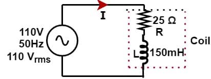
resistance of 25 Ω is connected to a 110V 50Hz supply.
Calculate:
a) the impedance of the coil, b) the current,c) the power factor and d) the apparent power consumed.
Also, draw the resulting power triangle for the above coil.
R = 25 Ω
Z = √ ( R2 + XL2) = √ ( 252 + 47.12) = 53.32 Ω
The impedance of the coil is Z = 53.32 Ω
b) The Current through the Coil
Cosɸ = R/Z = 25/53.32 = 0.46
ɸ = Cos-1 (0.46) = 62.61°
Sinɸ = √ ( 1 – Cos2ɸ) = √ ( 1 – 0.462) = 0.88
Reactive Power = VI Sinɸ = 110 x 2.06 x 0.88 = 199.40 VAr
Apparent Power = √ ( Active Power2 + Reactive Power2 )
= √ ( 104.232 + 199.402 ) =224.99 VA