I/P converter is a current to pressure transducer that works on the flapper nozzle method. I/P converter translates the input 4 to 20mA current signal into equivalent output of 3 to 15 PSI pressure.
Pneumatically operated control valves require a converter or transducer to change the proportional electrical signal to a proportional pneumatic signal. Generally, the converter comes as part of the valve.
In some instances, the converter is a separate part mounted near the valve.
Purpose of I/P Converter
Its purpose is to convert the analog signal output of a control system into an accurate repeatable value of pressure to control pneumatic actuators/operators, pneumatic valves, dampers, vanes, etc.
I/P converter produces a faultless, perfect, reliable, and repeatable process of converting an electrical signal to a pneumatic pressure in many control systems.
Mounting of I/P Converter
We should install the converter in a place where a technician can approach easily for attending repairs. Therefore, we mount the converter in the pipeline.
- We can mount the I/P converter on the wall,
- On pipe support or directly on the valve actuator.
- We can mount it directly on the valve actuator when it is capable to withstand vibration.
- In many cases, the device is mounted remotely on instrument mounts in pipes to reduce vibrations.
Signal Range
A current to-pressure (I/P) transducer converts an analog signal (4-20mA) to a linearly proportional pneumatic output signal in the range (3-15psi). The proportional electrical signal is generally a 4-20mA current signal, and the air pressure signal is generally 3-15psi.
We call the converter I/P converter because it changes a current signal (I) to a pressure signal (P).
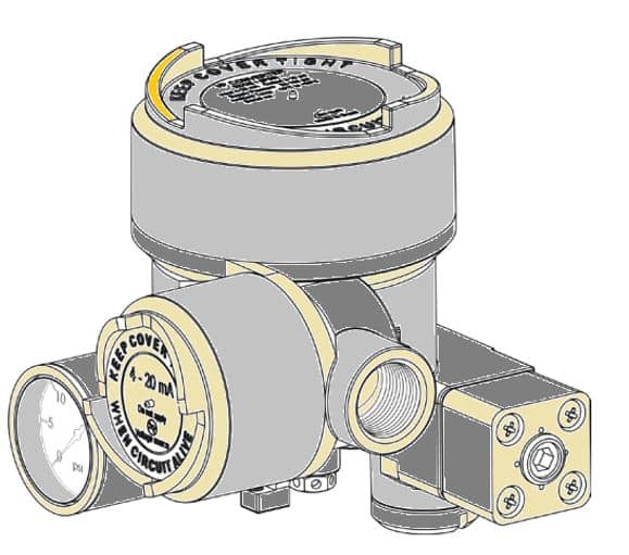
Working principle
A typical I/P transducer is a force balancing device in which a current flowing through the coil generates the movement of the flapper plate. It is an electromagnetic coil, used to change the position of a flapper plate that controls a small amount of pilot air pressure. The pilot air pressure controls the main air pressure to regulate it at 3-15 psi. The air supply for the I/P converter should be about 20 psi so that the converter can control pressure between 3-15 psi.
Relationship between Current and Pneumatic signal
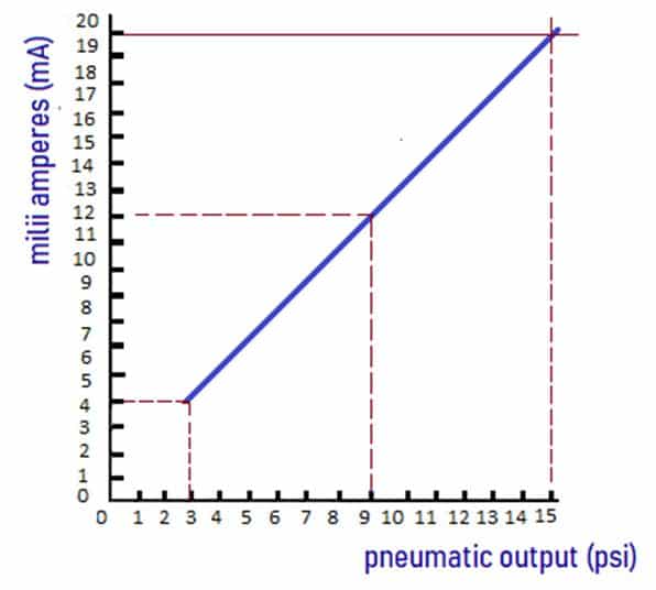
A graph showing the relationship of current to air pressure. The above graph allows for a selection of a current signal value in milliamps and determines the amount of air pressure the I/P converter should produce.
For example, when the electrical signal is at its minimum value (4 mA), the air pressure signal will also be at its minimum value (3 psi). Also when the electrical signal is at its maximum limit (20 mA), the air pressure signal will be at its maximum (15 psi). The midpoint value of the electrical signal is 12 mA, which provides 9 psi.
Operation of I/P converter
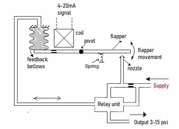
I/P converter uses a principle of forces in electromagnetic balance to change electrical signals into pneumatic signals. Typically I/P converter converts 4- 20 mA current input into 3- 15 psi output.
As shown in the diagram, as with the change of the current signal, the coil generates a magnetic field. The Flapper of the flapper nozzle has a connection to Pivot so that it can move up and down.
One piece of magnetic material has its attachment to the other end of the flapper, and we position it near the electromagnet. With the activation of the magnet, the flapper moves towards the electromagnet, and consequently the nozzle closes according to the current signal. Feedback bellows helps to provide balance in backpressure as with motion of flapper due to current signal.
How does a I/P converter work?
The input current flows in the coil and produces an attractive force of the flapper plate. More the current signal, the more the attraction towards the nozzle. Hence air backpressure will also be more. Thus, the spring balances the flapper plate to avoid the effect of shocks, unwanted vibrations on the flapper plate.
We can do its zero-point adjustment by turning a screw that regulates the distance between the flapper plate and the air nozzle. The zero adjustment causes the flapper to move relative to the nozzle.
The sensitivity (span) adjustment is a current adjustment with a potentiometer that limits the current through the coil.
A flapper valve of l I/P transducer receives an instrument air pressure of at least 20 psi. It calibrated for 4-20 mA input = 3-15 psig output. Usually, most of the I/P transducers are configurable for direct-acting (increasing output pressure as input signal increases).
In the event of failure of an electrical signal, the output signal of an I/P transducer easily drops to stall pressure. This makes it easy to detect the power failure signal on the device.
Application of I/P converter
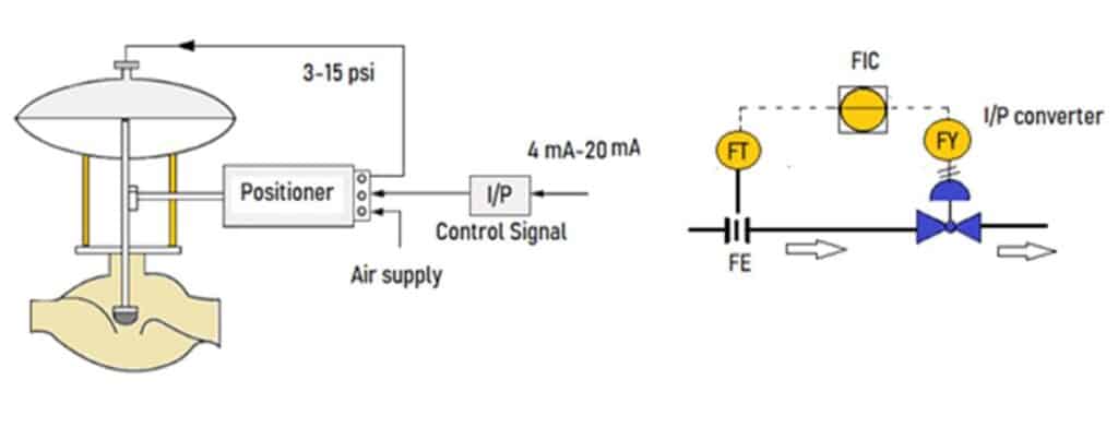
The controller output sends an electronic signal to the current-to-pressure (I/P) transducer, which in turn sends a pneumatic signal to the control valve. The control valve changes position in response to the signal to adjust the flow rate to the set point. As the flow changes. It is detected by the flow transmitter.
As long as the detected flow is equal to the set value, the valve position will remain the same. Whenever there is a system disturbance or set-point change, the flow control automatically responds to reach the programmed set point.
Read Next
Great ideas, looking for more knowledge.
thank you