In this article we will discuss importance and use of knee point voltage of current transformer in the protection circuit. The knee point voltage of CT is very important parameter that needs to be checked before using the CT in an electric circuit.
What is Knee Point Voltage(KPV)?
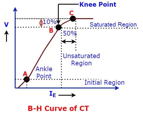
Knee point voltage is the voltage at which a 10% increase in applied voltage causes a 50% rise in the magnetizing current of a current transformer (CT). It defines the saturation limit of the CT, beyond which it cannot operate reliably — making it a critical parameter for protection-class CTs.
As per IEC, the knee point voltage is defined as the voltage at which a 10% increase in applied voltage increases the magnetizing current by 50%. For voltages greater than the knee point voltage, the magnetizing current increases considerably even for small increments in voltage across the secondary terminals.
IEEE defines saturation as “the point where the tangent is at 45 degrees to the secondary exciting amperes”. Also known as “knee” point.
The KPV shows the saturation limit of the current transformer. When CT goes into its saturation region, the core of the CT is no longer able to confine the magnetic flux in the core. Under saturation, the CT behaves as an open circuit, and its output is zero.
Therefore, the protection class CT must operate in its non-saturation region.
To ensure the operation of the CT in the non-saturation region, we need to calculate the maximum allowable secondary winding voltage limit up to which CT remains in its non-saturation region.
CT Magnetization Curve and Graph of KPV
CT magnetization curve and graph of KPV help visualize the linear and saturation zones of a current transformer.
This curve is important for understanding how the magnetizing current behaves with increasing secondary voltage and identifying the knee point accurately.
How to Test Knee Point Voltage of CT
The secondary of the current transformer is connected to an alternating voltage source (AC), while the CT’s primary is left open.
The knee point voltage (KPV) testing setup is shown below.
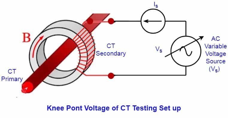
As the secondary voltage increases, keeping the primary of CT open, the current in the secondary increases with the increase in voltage.
At a particular voltage, the secondary current increases drastically, and that point corresponds to the KPV of CT.
The secondary voltage is increased by 10 % in steps, and the corresponding current is measured.
The point where the 10 % increase in the voltage causes a 50 % increase in the current is the knee point voltage of CT.
CT Test Results: Voltage vs Current
The following table shows how the secondary current varies with increasing voltage during KPV testing:
| Secondary Voltage (Volt) | Secondary Current (Ampere) |
| 3 | 0.001 |
| 7.5 | 0.002 |
| 12.5 | 0.003 |
| 18 | 0.004 |
| 60 | 0.01 |
| 150 | 0.02 |
| 200 | 0.025 |
| 235 | 0.03 |
| 300 | 0.05 |
| 356 | 0.08 |
| 372 | 0.01 |
| 400 | 0.15 ( CT Saturation Point) |
| 447 | 1.0 |
Why Knee Point Voltage is Important for CTs
The knee point voltage parameter is very important for protection class current transformers, especially for Class-PS, which is a special-purpose current transformer used for zone protection.
The CT used for protection and differential protection has to carry 20 to 30 times the CT-rated current during fault conditions.
If the CT saturates during fault conditions:
- The protection relay may not trip the breaker
- It may cause heavy damage to the electrical network
Knee point Voltage is very important in view of instrument safety factor.
The KPV of CT must be known for the protection class CT and PS (Protection Special) class CT.
Conclusion
Knee point voltage is a critical parameter in the selection and application of protection-class current transformers.
It defines the saturation threshold of the CT, ensuring that it operates accurately under high fault currents without distortion.
Proper understanding and testing of the knee point voltage help in designing a reliable protection scheme, especially for differential and zone protection systems.
Selecting a CT with the correct KPV ensures safe, efficient, and effective operation of protective relays in power systems.
Related Articles:
- How to Calculate Knee Point Voltage of Current Transformer?
- What is CT Burden? CT Burden Formula
- PS Class CT Specifications & its applications
- What is PS Class CT? Its Characteristics
- Why PS Class Current Transformer is used for Differential Protection?
- Magnetization Curve of CT
- Accuracy Class Of Current Transformer
- Can Protection CT be used as Metering CT & Vice Versa?
Nice 👍 contents.