A universal motor can be defined as a motor that can be operated on both AC and DC supply. The internal design of the motor is such that the nature of the voltage supply has no significant effect on the working of the motor except for the losses, which are different with different types of supplies.
Universal motors are well known for their high starting torque and high-speed operation. This is one of the reasons why these motors are preferred for traction and loading purposes.
Construction of Universal Motor
A universal motor, in general, is nothing but a DC Series Motor. Thus, having a thorough understanding of the design and working of a DC series motor is of great importance to understand the overall aspect of a universal motor.
Like any other DC motor, a universal or DC Series motor has two windings – the field winding on the stator and the rotatory armature winding. As the name says, the field and armature winding are connected in series, thus allowing the same current to flow through both the armature and the field winding.
As a universal motor is also expected to work on AC, it is designed to handle power losses due to AC, like the eddy current losses for which laminated core or the magnetic path is used. Similarly, the Hysterisis loss is also taken care of.
The rotating armature is wound type with skewed or straight slots and a commutator with high resistance brushes resting on it. The brushes have higher resistance as the commutation for AC supply is poorer than that of DC because of the current induced in the armature coils.
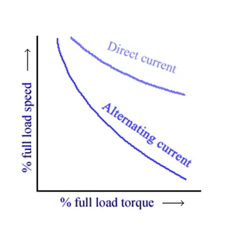
Universal Motor Diagram
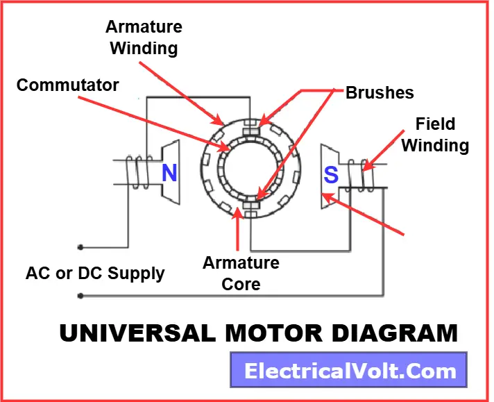
A universal motor is made up of several key components that work together to allow the motor to run efficiently on both AC and DC supplies. The major parts include the frame, field core, field winding, armature, and brushes. Each of these parts has a specific function, explained below:
1. Frame
The frame of the motor is the outer body that holds all the internal parts together. It is usually made of rolled steel or cast iron for durability and rigidity. Apart from providing mechanical strength, it also serves as protection for the inner components against dust, dirt, and external damage.
2. Field Core
The field core is made of thin laminated sheets to minimize eddy current losses when the motor is used on AC supply. The core contains field poles (generally two-pole for small machines) that produce the necessary magnetic path for flux.
3. Field Winding
The field winding is wound around the field poles of the core. When current passes through it, the winding produces the magnetic flux required for motor operation. In a universal motor, the field winding is connected in series with the armature winding, which helps generate high starting torque.
4. Armature
The armature is the rotating part of the motor. It consists of a laminated iron core with either straight or skewed slots to reduce magnetic losses and improve smoothness of rotation. The slots hold the armature winding, which is connected to the commutator. As current flows through the winding, it interacts with the magnetic field to produce torque, causing the rotor to spin.
5. Commutator
The commutator is attached to the armature and is made of copper segments insulated from one another. It plays a vital role in reversing the current direction in the armature conductors, ensuring that the motor produces unidirectional torque even on AC supply.
6. Brushes
The brushes are made of carbon or graphite and are placed on the commutator surface. Their role is to maintain electrical contact between the stationary external circuit and the rotating commutator. Brushes ensure smooth transfer of current to the armature winding, though they also cause frictional losses and require periodic replacement.
- In some universal motors, compensating windings are added to counteract reactance voltage and improve commutation on AC supply.
- Bearings are fitted at both ends of the shaft to support the rotating armature and reduce friction during high-speed operation.
Working of Universal Motor
A DC series motor is a universal motor because it can work on AC and DC supplies, even though the name suggests it to be a DC motor. This is because, unlike other DC motors that vibrate or fail to work on AC supply, a DC series motor can generate positive torque for both positive and negative voltage supply.
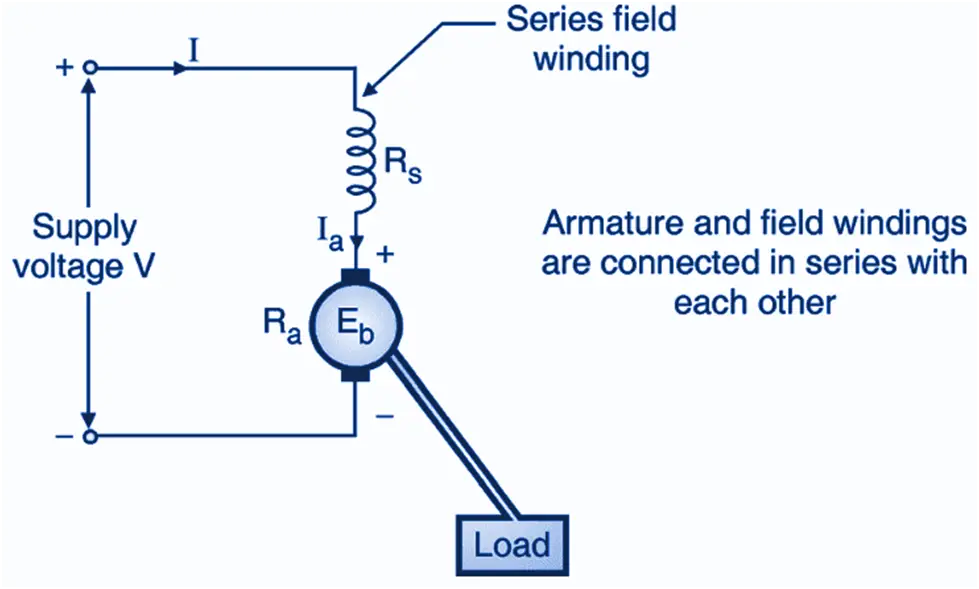
To understand how that happens, we need to learn about the working of the internal circuit of a DC series motor, as shown above.
A series motor has both armature and field winding connected in series. Because of this, the armature current is equal to the field current, which is nothing but the source current.
The following expression gives the torque generated by a universal motor.
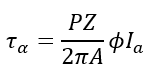
Where
Tα =T Torque of the motor in Newton-metres.
P = No. of poles
Z= Number of armature conductors
A= The Number of parallel paths
Ia= Total current through the armature conductors
ϕ=Magnetic field flux per pole
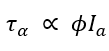
The number of parallel paths, the number of poles, and the number of armature conductors in a given machine are constant. Therefore, the torque generated by a universal motor is directly proportional to the magnetic field flux per pole and the armature current. Thus,
The magnetic field flux per pole is generated due to the current passing through the field coil, which can be denoted by If. Hence, we can say that.

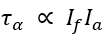
Therefore, the torque generated by a DC motor can be said to be directly proportional to the product of the armature and the field current.
In the case of a DC Series motor, the field and the armature windings are connected in series. Thus, the current flowing through both windings is equal to the source current, as evident from the circuit diagram above.
So, the source current is,
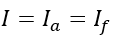
Therefore, the torque generated by the series motor is
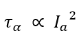
Therefore, in a DC series motor, the generated torque is directly proportional to the square of the armature current (or the field current). This is the primary reason why this motor can be operated on both DC and AC supply.
In the case of a DC supply, the voltage has no polarity, while in the case of an AC supply, the voltage is positive for one-half cycle and negative for another half cycle. As the torque of the DC series motor is proportional to the square of the armature current, the torque generated by the motor is always positive. This is what makes a DC series motor eligible to be called a universal motor.
Types of Universal Motors
Universal motors are broadly classified into two types: compensated and non-compensated motors. Both are capable of operating on AC and DC supplies, but their construction and performance differ.
Non-Compensated Universal Motor
The non-compensated type is the simpler version of a universal motor. It is constructed with two wide laminated poles, which help reduce eddy current losses when running on AC supply. The armature core is laminated and designed with straight or skewed slots where the windings are placed.
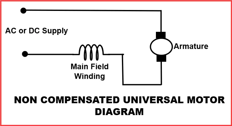
The winding leads are connected to the commutator, and the motor uses high-resistance carbon brushes to achieve smoother commutation. These brushes help minimize sparking, especially under AC operation where commutation is more difficult compared to DC.
This type of universal motor is generally used in low-power appliances where compact design and cost-effectiveness are important.
Compensated Universal Motor
The compensated type is an improved version of the universal motor. In this design, the stator core includes an additional compensating winding, which is embedded in slots located at right angles to the main field winding.
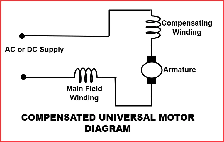
The purpose of this extra winding is to neutralize the reactance voltage produced in the armature due to alternating current. As a result, compensated motors offer:
- Better commutation
- Reduced sparking at brushes
- Improved efficiency on AC supply
These motors are often used in high-power applications where smooth operation and long service life are required.
Torque and Speed Characteristics
As the motor’s torque is directly proportional to the square of the armature current, the universal motor is known for its high starting torque. This can be better understood by considering the voltage equation of the motor given as
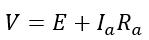
Where V is the source voltage, E is the back-emf of the motor, and Ia and Ra are the armature current and armature resistance, respectively.
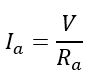
As evident from the equation, the motor’s back EMF reduces the armature current. This back EMF is directly proportional to the speed (rpm) of the universal motor. Therefore, when the motor speed is almost zero, the motor’s back EMF remains zero at the starting point. Thus, the current flowing through the armature is maximum at the starting point given as
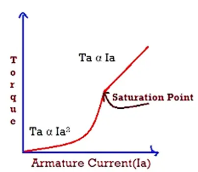
As the torque generated by the DC series motor is directly proportional to the square of the armature current, the starting torque of the DC series motor is extremely high.
Beyond a certain value of the source current, the field coil saturates. Therefore, the torque of the universal motor is no longer directly proportional to the square of the armature current. There is a linear relation between the torque and the armature current henceforth.
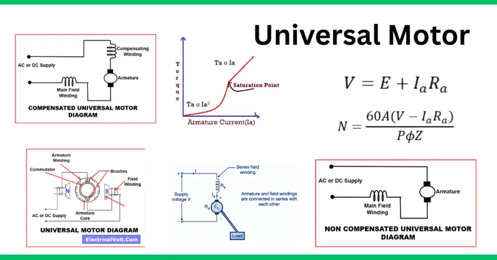
The speed of the motor is given by
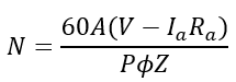
As evident, the speed of the motor is inversely related to the field flux per pole. In a series motor, as discussed earlier, the field flux is directly proportional to the field current, which is equal to the armature current. This armature current rises as the load on the motor rises.
Therefore, at no load condition, the motor attains a dangerously high speed (ideally infinite, as the armature current is zero. That’s why a universal motor shouldn’t be operated without load.
The universal motor is known for its high-speed performance. The following curve gives the torque-speed characteristics of a universal motor.
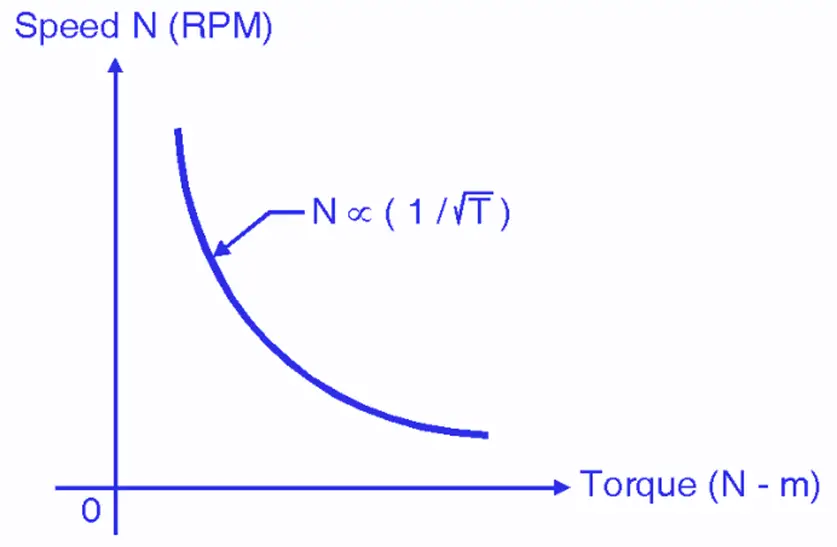
The following curve gives the speed-torque characteristics of a universal motor for both AC and DC supply.
Universal Motor Speed Control
A universal motor is capable of running at very high speeds, sometimes reaching 20,000 RPM or more. However, at no-load conditions, the motor can accelerate to dangerously high speeds because there is no counteracting load to balance the torque. Therefore, proper speed control is essential to ensure safe and reliable operation.
To manage this, universal motors are often paired with a gear train, which reduces the high motor speed to a more practical level suitable for the driven load (for example, in mixers, drills, or sewing machines).
The common methods of speed control in universal motors are:
Centrifugal Mechanism
A centrifugal governor is mounted on the motor shaft. When the motor speed increases beyond the safe limit, the governor activates and adjusts the circuit to limit the voltage or current supplied to the motor. This automatic action prevents the motor from running at unsafe speeds.
Resistance Method
In this method, an external resistance is connected in series with the motor. By varying this resistance, the current flowing through the armature and field can be controlled, thereby adjusting the motor speed. While simple, this method is less efficient because a portion of the input power is wasted as heat in the resistance.
Field Tapping Method
In this method, taps are provided in the field winding. By selecting different taps with a switch, the effective number of turns in the field coil is changed. This alters the field flux and, consequently, the motor speed. A lower number of field turns weakens the flux, which increases the motor speed, while more turns strengthen the flux and reduce the speed.
Additional Modern Speed Control Approaches
- Electronic Speed Control (using Triacs or SCRs): Widely used in household appliances, this method adjusts the RMS voltage applied to the motor, allowing smooth variation of speed with minimal energy loss.
- Pulse-Width Modulation (PWM): In advanced tools and appliances, PWM control provides precise and efficient speed regulation by controlling the duty cycle of the input supply.
Variants of Universal Motors
Over time, engineers experimented with different versions of the universal motor to improve its performance, commutation, and starting torque. Although most universal motors today are of the series-wound type, two notable variations were explored in the past: Shunt-Wound Universal Motors and Repulsion Start Motors.
Shunt-Wound Universal Motor
The shunt variation of the universal motor was experimented with as early as the 19th century. In this design, a shunt winding was added in parallel with the armature winding. The idea was to provide better speed regulation and smoother operation.
However, this design suffered from poor commutation issues, especially on AC supply. Engineers tried various methods such as:
- Introducing embedded resistance
- Adding inductance in the circuit
- Using anti-phase cross-coupling techniques
Despite these efforts, the shunt-wound universal motor could not match the simplicity and robustness of the series-wound type. Still, it had one advantage—it was capable of self-starting without external assistance.
With the introduction of induction motors and automatic starters, shunt-wound universal motors were eventually phased out.
Repulsion Start Motor
The repulsion start motor was another important variation. It was designed to deliver very high starting torque, which made it suitable for heavy-duty applications.
Key features of this design included:
- A rotor similar to that of a universal motor.
- Brushes connected only to each other (not to the supply).
- Torque generated through the principle of repulsion between the rotor’s induced currents and the stator field.
Although effective in producing strong torque, this design was mechanically more complex and eventually replaced by simpler universal motors and other types of AC machines.
Note:
- Modern universal motors no longer use these variations because of the availability of electronic speed controllers and improved commutator designs, which make the standard series-wound universal motor far more efficient and reliable.
- These experimental designs, however, played a key role in the evolution of motor technology during the early stages of electrification.
Advantages & Disadvantages of Universal Motor
The universal motor is highly versatile, capable of operating on both AC and DC power, offering high starting torque, compact size, and easy speed control, making it ideal for portable and domestic applications. However, it also has disadvantages, including high noise, shorter lifespan, frequent maintenance, overheating during prolonged use, and lower efficiency at high speeds, which should be considered when selecting it for a specific application.
Read detailed article: 12 Advantages and Disadvantages of Universal Motors
Applications of Universal Motor
Universal motors are widely used because they are compact, inexpensive, and capable of running at very high speeds on both AC and DC supply. Their ability to deliver high starting torque makes them suitable for a variety of domestic and industrial applications.
Common Applications:
- Household Appliances: Vacuum cleaners, food mixers, blenders, electric shavers, hair dryers, and sewing machines.
- Portable Tools: Drills, grinders, sanders, and saws where high-speed operation is required.
- Automotive Uses: Windshield wipers, portable fans, and other auxiliary devices.
- Industrial Uses: Light machine tools, high-speed conveyors, and equipment requiring compact high-RPM drives.
Application by Motor Rating:
- Small-sized universal motors → Preferred for compact domestic devices like shavers, fans, and sewing machines.
- Higher-rated universal motors → Used in heavy-duty appliances and tools such as portable drills, sawmills, and professional blenders.
By combining high speed, high torque, and compact design, universal motors remain one of the most versatile types of motors used in day-to-day appliances and portable power tools.
Difference Between DC Series Motor and Universal Motor
A DC series motor operates only on DC supply, has very high starting torque, load-dependent speed, and uses a solid core in the armature and field winding. It is commonly used in heavy-duty applications like cranes and elevators. A universal motor can run on AC or DC, offers high-speed operation, moderate starting torque, and uses a laminated core to reduce eddy current losses on AC supply. It is typically used in portable appliances like mixers, drills, and vacuum cleaners.
Read detailed article: Difference Between DC Series Motor and Universal Motor
Conclusion
A universal motor is a versatile machine capable of running on both AC and DC supply with high starting torque and speed. Its compact design, simple construction, and adaptability make it widely useful in household appliances, portable tools, and light industrial equipment. Despite some limitations like high noise and maintenance, its efficiency and performance keep it a preferred choice in many everyday applications.
FAQs on Universal Motor
A universal motor is an electric motor that can run on both AC and DC supply, known for high speed and strong starting torque.
It works like a DC series motor, with armature and field windings in series, producing torque in the same direction on both AC and DC.
It is compact, low-cost, delivers high starting torque, and can run at very high speeds, making it ideal for portable tools and appliances.
The two main types are non-compensated universal motors (simpler, for small appliances) and compensated universal motors (better AC performance).
Yes, but it is not practical due to poor efficiency and commutation issues.
A DC motor runs only on DC supply, while a universal motor can run on both AC and DC, usually at much higher speeds.
Related Articles:
- Difference between AC and DC Motor
- Characteristics of a Stepper Motor
- Losses in Induction Motor
- 3 Phase Induction Motor | Definition And Working Principle
- Hunting in Synchronous Motor- Causes, Effects & Reduction
- What is a Printed Circuit Board(PCB) Motor? Its Construction, Working
- 12 Advantages and Disadvantages of Universal Motors | Applications
- Difference Between DC Series Motor and Universal Motor