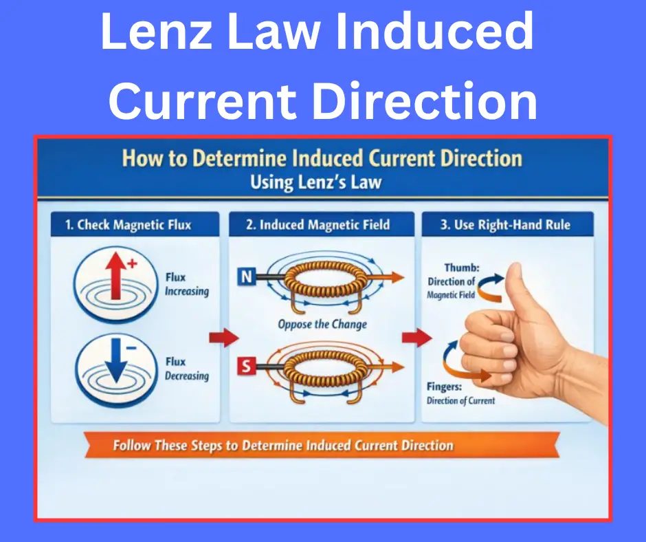
- Lenz’s Law Explained: Lenz’s Law states that the induced current in a conductor flows in a direction such that the magnetic field it generates opposes the change in the magnetic field that caused it.
- Electromagnetic Induction Principle: Electromagnetic induction occurs when a changing magnetic field around a conductor produces an electric current.
- Significance of the Negative Sign: The negative sign in Faraday’s Law indicates that the induced EMF acts in a direction opposing the variation in magnetic flux.
- Practical Applications: Lenz’s Law is essential in devices like electric motors, generators, and induction systems, explaining resistance to motion due to electromagnetic effects.
- Energy and Force Balance: This law reflects the conservation of energy and aligns with Newton’s Third Law, ensuring that magnetic and mechanical interactions counterbalance each other.
Lenz’s law of electromagnetic induction states that the changing magnetic field causes the direction of induced current in such a way that it opposes the change in the magnetic field.
Electromagnetic induction is one of the most important principles in electrical engineering, forming the foundation of how a wide range of electrical machines operate. Whether the machines are large or small, stationary or rotating, their working is largely based on the laws of electromagnetic induction. In everyday life, we are constantly surrounded by numerous devices and appliances—often without realizing it—that rely on this fundamental phenomenon to function efficiently.
Meaning of Electromagnetic Induction
Electrical and magnetic forces occur simultaneously in nature. These two forces are like two sides of the same coin, co-existing across space and time. The presence of one is inseparable from the other, which is why this combined phenomenon is known as electromagnetism.
In electrical engineering, greater emphasis is placed on time-varying electric currents and changing magnetic fields rather than static ones. Induction refers to the mutual influence between electric and magnetic phenomena—it may involve the effect of a magnet on a current-carrying conductor or the effect of an electric current on a magnetic field. These interactions are clearly explained through the laws of electromagnetic induction.
Laws of Electromagnetic Induction
Faraday’s First Law of Electromagnetic Induction states that an induced EMF is generated in a current-carrying conductor whenever it is exposed to a time-varying magnetic field. This variation in the magnetic field experienced by the conductor can occur in two ways:
- When the magnetic field rotates relative to the conductor.
- When the conductor rotates relative to the magnetic field.
Faraday’s Second Law of Electromagnetic Induction explains the magnitude of the induced EMF, stating that it is directly proportional to the rate of change of magnetic flux linked with the conductor or coil.
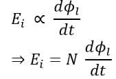
Where:
- E = induced EMF
- N = number of turns in the coil
- Φ = magnetic flux linked with the conductor, which is equal to the product of the number of turns in the coil and the associated magnetic field flux.
What is Lenz’s law?
The German scientist H. F. E. Lenz formulated Lenz’s Law, which explains the direction of the induced EMF in a coil. According to this law, the induced EMF generated by a time-varying magnetic field always acts in a direction that opposes the very cause of its own generation.
In simple terms, Lenz’s law means that the induced current always flows in a direction that tries to oppose the change in the magnetic field that produced it.
Lenz’s Law of Electromagnetic Induction Explained
Lenz’s Law states that the induced EMF in a coil, caused by a time-varying magnetic field, always acts to oppose the magnetic field that produced it.
A time-varying magnetic field induces an EMF within a coil, and if the coil forms a closed circuit, this EMF produces a current. The induced current, in turn, generates its own magnetic field, with a polarity that opposes the original magnetic field responsible for the induction. In this way, the induced EMF resists the very cause of its creation, in accordance with Lenz’s Law.
Case 1: When a magnet is moving towards the coil.
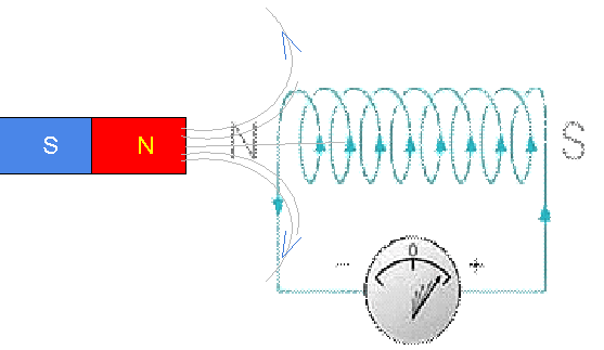
In the illustration, the magnetic North pole moves toward the coil, resulting in the generation of an induced EMF within the coil.
As the north pole of a magnet approaches a closed coil, the magnetic flux linked with the coil increases. In accordance with Faraday’s law of electromagnetic induction, this change in flux induces an electromotive force (EMF), causing a current to flow through the circuit. The induced current generates its own magnetic field around the coil.
According to Lenz’s law, this newly produced magnetic field always acts to oppose the change in magnetic flux that created it. To resist the increasing flux due to the approaching north pole, the face of the coil nearest to the magnet develops north polarity. As a result, the coil’s magnetic field repels the magnet’s north pole, thereby counteracting the original magnetic field.
When the circuit is closed, the direction of the induced current can be determined using Fleming’s Right-Hand Rule. In this case, the rule shows that the current flows in an anticlockwise direction, producing the opposing magnetic field that resists the motion of the magnet.
Case 2: When a magnet is moving away from the coil
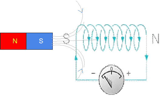
When the north pole of a magnet moves away from a coil, the magnetic flux linked with the coil decreases. According to Faraday’s law of electromagnetic induction, this change in flux induces an electromotive force (EMF) in the coil, which leads to the flow of an induced current. This current generates its own magnetic field around the coil.
As stated by Lenz’s law, the magnetic field produced by the induced current always acts to oppose the change in magnetic flux responsible for its formation. To counter the decreasing flux caused by the receding magnet, the face of the coil nearest to the magnet acquires south polarity.
Consequently, the induced magnetic field is oriented such that the south pole of the coil faces the south pole of the magnet, resulting in repulsion between like poles. This repulsive force resists the magnet’s motion away from the coil and thereby opposes the decrease in flux.
After identifying the magnetic polarity developed on the coil, the direction of the induced current can be determined using the right-hand rule. In this situation, the induced current flows in a clockwise direction.
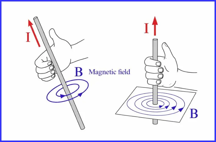
To apply the right-hand thumb rule, hold the conductor with your right hand such that the thumb points in the direction of current flow. The curved fingers then indicate the direction of the magnetic field produced around the conductor.
Lenz’s Law Formula
The Lenz’s Law Formula is expressed mathematically by adding a negative sign to the time-varying magnetic field in Faraday’s Law of Electromagnetic Induction.
The Lenz’s Law formula is represented as follows:
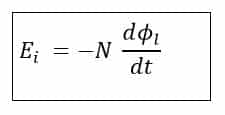
The negative sign indicates that the induced EMF acts to oppose the cause that produced it, which is the time-varying magnetic field.
While this concept applies to a magnetic flux generated by a permanent magnet, in electrical machines, the time-varying magnetic field is created by a time-varying current flowing through an inductive circuit. In this case, the linked magnetic flux is equal to the product of the coil’s inductance (or inductor) and the instantaneous current passing through it.
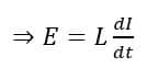
In this case, the induced EMF is given by:
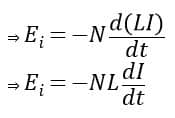
Here, L represents the inductance of the coil, and I denotes the instantaneous current flowing through the coil. The inductance L is a constant that depends on the physical characteristics of the coil, while the instantaneous current I represents the current at a specific moment in time.
Since the current is time-varying, the value of I changes with time and therefore is not constant.
The inductance (L) of a coil is given by the formula:
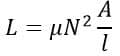
Where,
µ =permeability in Wb/A.m
N =Number of turns
A = cross-sectional area of the coil (m2)
l = Length of the coil (m)
L = Inductance measured in Henry(H).
Now, let us determine the equation of the current flowing through a purely inductive circuit.
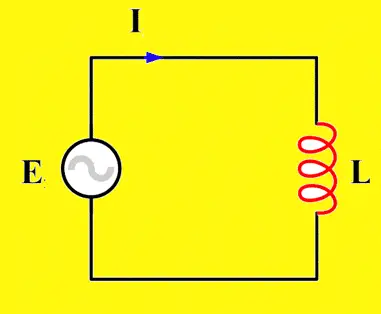
By applying Kirchhoff’s Voltage Law (KVL) to the circuit, we get the relation:
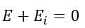
Here, E represents the instantaneous source voltage, which varies with time. Therefore, the equation can be expressed as:
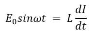
Where ω is the angular frequency given by ω=2πf, f= source frequency in Hz.
Now,
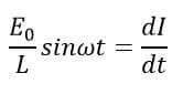
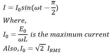
Integrating both sides of the equation with respect to time (t), we get the expression for the instantaneous current in a purely inductive circuit:
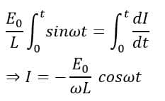
Now,
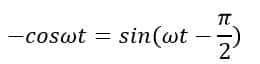
Therefore,
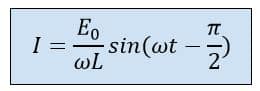
Therefore, in a purely inductive circuit, the instantaneous current lags the source voltage by 90°. This relationship can be simply written as:
Thus, by applying Lenz’s Law of Electromagnetic Induction, we can determine the instantaneous current in a purely inductive circuit. In contrast, in a purely resistive circuit, the current remains in phase with the applied voltage.
However, in a purely inductive circuit, the current lags the source voltage because the EMF induced by the inductor opposes the very cause of its creation—that is, the flow of current through it. This phase lag can be reduced by adding resistance or a combination of resistance and capacitance to the circuit, which modifies the overall impedance and reduces the current’s delay relative to the voltage.
Lenz’s law and Conservation of Energy
According to the Law of Conservation of Energy, energy can neither be created nor destroyed; it can only be converted from one form to another. Lenz’s Law of Electromagnetic Induction reflects this principle. According to Faraday’s Second Law of Electromagnetic Induction, the induced EMF is directly proportional to the rate of change of magnetic flux passing through the coil.
This means that if the coil is connected in a closed circuit, the induced EMF will produce a current flowing through both the circuit and the coil. This induced current generates its own magnetic field, which interacts with the original magnetic field. If the induced field were to reinforce the original field, it would continuously strengthen the magnetic field, leading to the generation of increasingly larger EMF—a scenario that violates the law of conservation of energy.
If this were allowed, the induced EMF would continually produce a current, which in turn would generate an even stronger magnetic field, creating a feedback loop of increasing energy.
This scenario would violate the Law of Conservation of Energy, as it implies a source of perpetual energy, which does not exist in nature. In reality, such an effect does not occur in an inductive circuit, because the induced EMF always opposes the change in magnetic flux, in accordance with Lenz’s Law.
That’s why the negative sign in Lenz’s Law reflects what actually occurs in nature, ensuring compliance with the Law of Conservation of Energy. Additionally, this behavior aligns with Newton’s Third Law of Motion, which states that for every action, there is an equal and opposite reaction.
Lenz’s law and Mechanical Inertia
One way to interpret Lenz’s Law is by comparing an inductive circuit to mechanical inertia. Just as inertia resists changes in the motion of a body, an inductor in an electric circuit opposes changes in the current flowing through it.
This effect is also evident from the equation of instantaneous current derived earlier, where the current lags the voltage by 90° in a purely inductive circuit. This occurs because the inductor resists changes in current, effectively acting as an “electrical equivalent of inertia.
Thus, Lenz’s Law of Electromagnetic Induction is highly significant, as it enables accurate modeling of circuits containing inductors. Using this principle, all AC machines can be analyzed effectively, just as demonstrated above for a purely inductive circuit.
Lenz’s Law Applications
The following are the key applications of Lenz’s Law:
- Using Lenz’s Law, we can clearly understand the concept of energy storage in inductors. When a voltage is applied to an inductor, it opposes the applied voltage by generating an induced EMF of opposite polarity, thereby resisting the flow of current. As a result, the source must do work to establish current through the inductor. When the applied voltage is removed, the energy stored in the inductor can be released back into the circuit.
- Lenz’s Law is also crucial in the operation of electric generators and electric motors. In a generator, the induced current opposes the mechanical rotation that produces it, requiring additional mechanical energy to maintain motion. In a motor, the induced EMF opposes the applied voltage, thereby limiting the current flowing through the motor.
- This Law is also applied in electromagnetic braking, where the induced currents in a conductor create magnetic fields that oppose motion, producing a braking force without physical contact.
- Lenz’s Law is utilized in induction cooktops, where a time-varying magnetic field induces eddy currents in the cooking vessel. These induced currents generate heat due to the vessel’s resistance, allowing for efficient and rapid cooking.
- This law provides a physical explanation for the negative sign in Faraday’s Law of Induction, indicating that the induced EMF always opposes the change in magnetic flux that produced it, in accordance with Lenz’s Law.
Read detailed article on: Applications of Lenz’s Law
Conclusion
Lenz’s Law of Electromagnetic Induction is a fundamental principle in electrical engineering that explains the direction of induced EMF in a conductor. According to the law, the induced current always flows in a direction that opposes the change in magnetic flux responsible for its generation.
This principle not only ensures energy conservation but also helps in understanding and designing electrical machines, generators, motors, induction systems, and other electromagnetic devices.
By applying the Lenz’s Law formula, engineers can accurately calculate induced EMF and predict the behavior of circuits under time-varying magnetic fields, making it a crucial concept for both theoretical studies and practical applications in modern technology.
Read Next: