This article describes the concept of commutation in DC machines, including DC generators and motors. Learn how it works, its importance, types, and methods to improve commutation for efficient operation.
What is Commutation in a DC Machine?
The armature winding of a DC generator generates an alternating voltage because it experiences a rotating magnetic field. Commutation in a DC machine, in the case of a DC generator– is the process of converting this alternating current into direct current with the use of a commutator and stationary brushes, and in the case of a DC motor– commutation is the process of converting the input direct current into alternating current AC in the armature with the use of a commutator and stationary brushes.
Commutation Period in a DC Machine
In a DC machine, the transfer of current from the rotating armature to the stationary brushes requires a continuous moving connection between the commutator segments and the brushes.
With the rotation of the armature, the coils under one magnetic pole (such as the north pole) go between a positive and a negative brush. During this process, current flows through these coils to the commutator segments.
Then the coil gets short-circuited for a short duration of about 1/500 the of a second. The duration for which the coil remains short-circuited is known as the commutation period. After commutation, the armature coil rotates under the south(S) pole and moves between a negative brush and the next positive brush.
During this rotation, the direction of the current reverses and it leaves through the commutator segment. The reversal of the current must happen at the end of the commutation period for ideal commutation.

Effects of Poor Commutation in DC Machine
When the current does not completely reverse at the end of the communication period, you can observe the sparking at the brush contacts. This can lead to overheating and may cause damage to the surface of the commutator. In this condition, you can term the commutation as poor commutation.
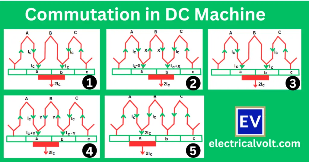
How Commutation in DC Machine Works
To explain the commutation process, we consider a DC machine with its armature having a ring winding. Assume that the commutator bar and the brush have the same width, and the current flowing through the conductor is denoted as IC.
With the rotation of the armature, let the commutator move from left to right, then obviously the movement of the carbon brush is from right to left because the brushes do not rotate and remain fixed.
Initial Position of Brush Contact
In the initial position, the brush makes contact with commutator bar b (as shown in Fig. 1). At this point, the total current flowing from commutator bar b to the brush is 2IC.
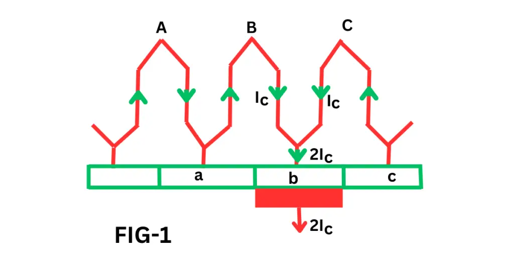
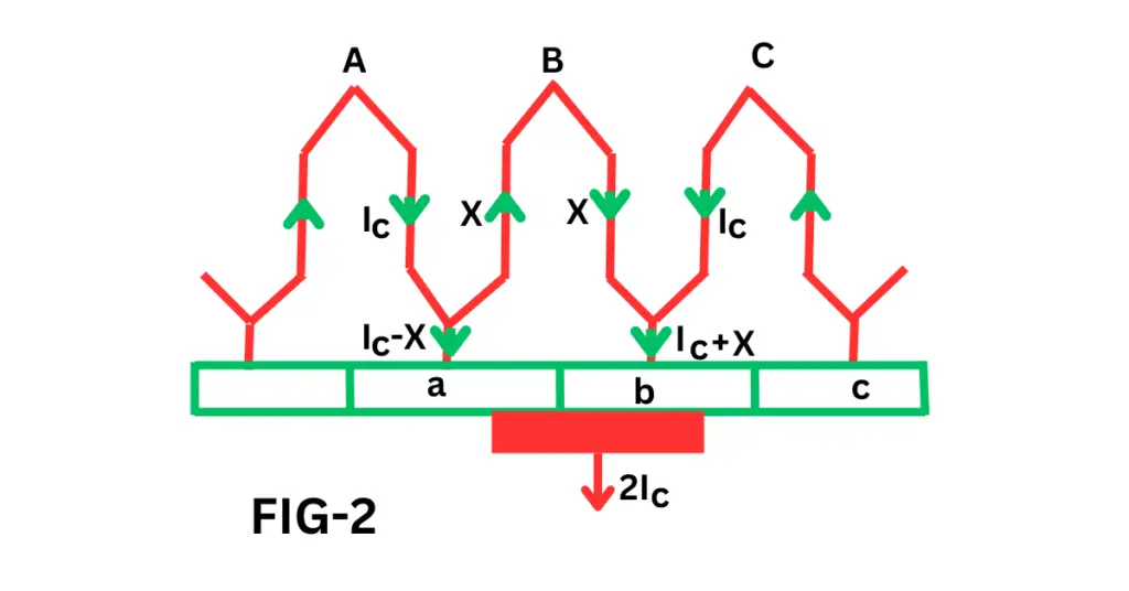
Current Division Between Two Paths
The brush comes into contact with the commutator bar when the armature moves to the right. At this point, the armature current divides and flows through two paths via bars a and b (as shown in Fig. 2). However, the total current (2IC) collected by the brush remains unchanged.
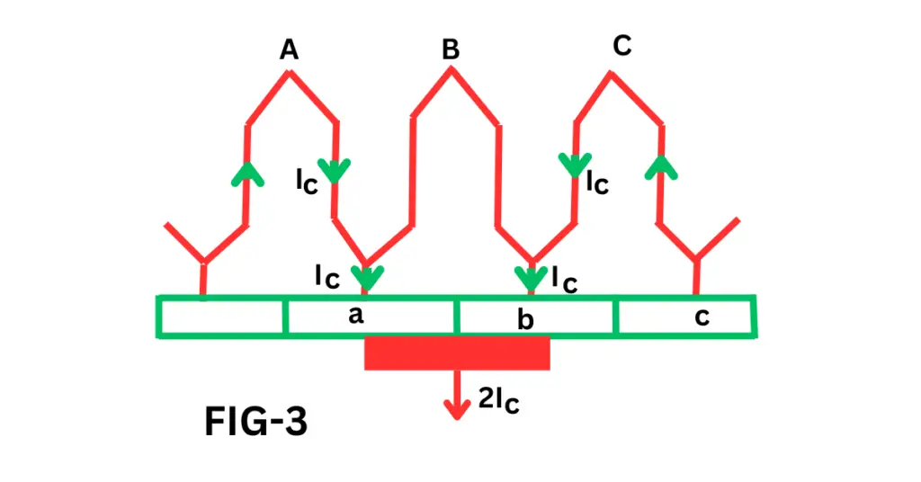
Equal Current Sharing
As the brush makes more contact with bar a and less with bar b, the current in bar A increases and the current in bar b decreases. When both bars have equal contact with the brush, the current divides equally between them (see Fig. 3).
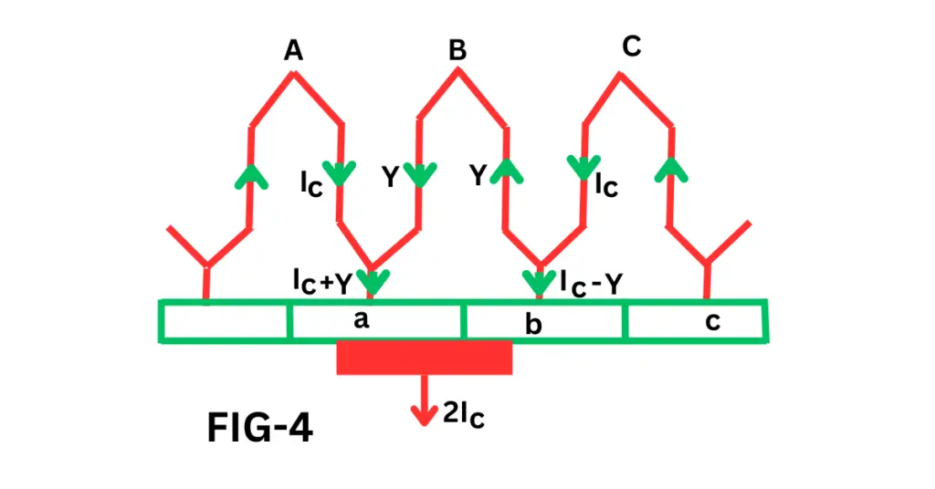
Current Reversal in Coil
The brush connected to bar b moves further and its contact area with bar b decreases and causes current through bar b to decrease. Finally, the current in coil B reverses its direction and starts to flow counter-clockwise (as shown in Fig 4).
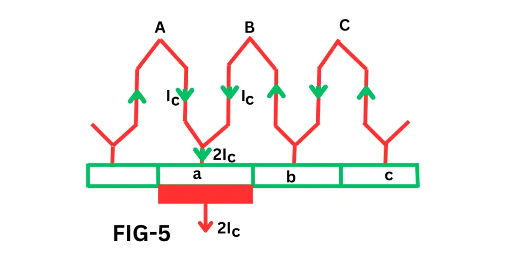
Completion of Commutation Process
When the brush makes full contact with bar A and disconnects from bar B, the current IC flows in a counterclockwise direction through coil B, breaking the short circuit (as shown in Fig 5).
Methods of Improving Commutation
Sparkless commutation can be achieved through three different methods, which help reduce sparking at the brushes and improve machine efficiency:
- Resistance Commutation: Adding resistance in series with the coil to smooth current reversal.
- Voltage Commutation: Using interpoles or induced EMF to assist current reversal.
- Use of Compensating Windings: Reduces the effect of armature reaction and ensures proper commutation.
Role of Commutator in DC Generator and DC Motor
The commutator is a crucial component in both DC generators and DC motors, serving different but related functions:
- In a DC Generator: The commutator converts the alternating voltage induced in the armature windings into direct current at the terminals. It ensures that the output delivered to the external circuit is smooth DC.
- In a DC Motor: The commutator reverses the current in the armature coils as they pass under different magnetic poles. This reversal keeps the torque in a single direction, allowing the motor to run smoothly and efficiently.
Proper operation of the commutator is essential for preventing sparking, reducing wear on brushes, and maintaining efficient performance in both DC generators and motors.
FAQs on Commutation in DC Machines
Commutation in a DC generator is the process of converting the alternating current induced in the armature winding into direct current with the help of a commutator and brushes.
In a DC motor, commutation is the process of reversing the current in the armature conductors so that continuous torque is produced in one direction.
The commutation process refers to the short time during which the current in an armature coil reverses as the coil moves under different magnetic poles.
Poor commutation causes sparking at the brushes, overheating, and damage to the commutator surface.
Related Articles: