Armature winding is the winding in which voltage is induced as the conductors of the coil pass through a magnetic field of the field winding. The armature winding can also produce a magnetic field when voltage is applied to it, interacts with the field winding flux, and causes the armature to rotate. Thus, the armature winding generates torque in motors or the voltage in generators.
Definition of Armature Winding
Basic Terms Related to Armature Winding
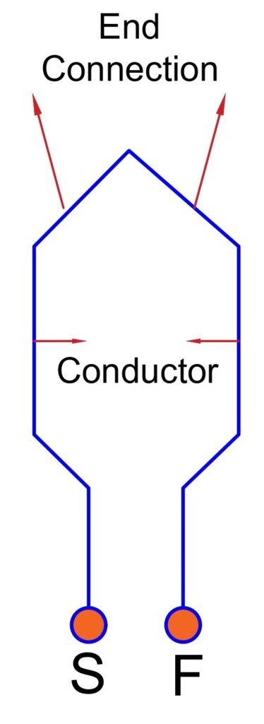
Turns
Each loop of wire around the core is a turn consisting of two conductors connected by an end connector. The one turn consists of two conductors. The diagram of the turn is shown below.
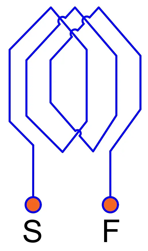
Armature Coil
A coil has several turns in the series. The turns of the conductors are connected in series- the end of one turn is attached to the beginning of the next turn, forming a continuous path for the flow of electrical current.
The beginning and end of the coil are identified by the symbols (S)-Start and (F)-Finish, respectively. The diagram of the coil is shown below.
Armature Winding
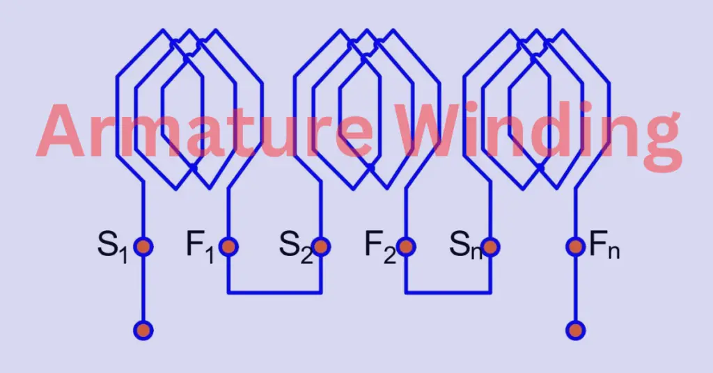
The multiple coils are connected in the series to form a winding. The figure of the armature winding is shown below.
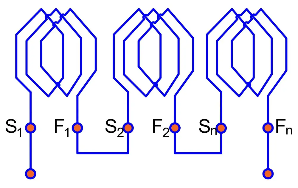
The beginning and end of the turn or coil are identified by the symbols (S), and (F), respectively. “S” and “F” are the abbreviations used to indicate the Start and Finish end of a coil.
The Finish end of the first coil is connected to the Start end of the second coil, and the Finish end of the second coil is connected to the Start end of the third coil. All the coils are connected in the series, making a single armature winding, and the same current flow through the winding.
Electrical Degrees
An electrical machine has a certain number of poles, and the coils are placed in the slots of the armature. Therefore, it is important to understand the concept of electrical degrees, pole pitch, and coil pitch when studying electrical machines.
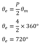
The electrical degree of a P-pole machine can be calculated using the following mathematical expression.
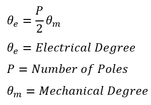
You can calculate the electrical degree of the 4-pole machine using the above formula.
The advantage of using electrical angle notation is that the expressions apply to machines with any number of poles.
Pole Pitch
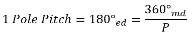
The peripheral distance between the centers of adjacent poles on a machine is known as pole pitch or pole span. The pole pitch is always 180 degrees electrical, regardless of the number of poles. The distance between two poles can be calculated using the following mathematical expression.
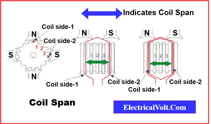
Coil Pitch (Coil Span) of Armature Winding
A coil consists of two sides that are placed in two slots on the stator surface. The distance between these two sides is referred to as the coil pitch or coil span.
- If the coil pitch equals one pole pitch, it is called a Full Pitch Coil.
- If the coil pitch is less than one pole pitch, it is called a Short Pitch (or Fractional Pitch) Coil.
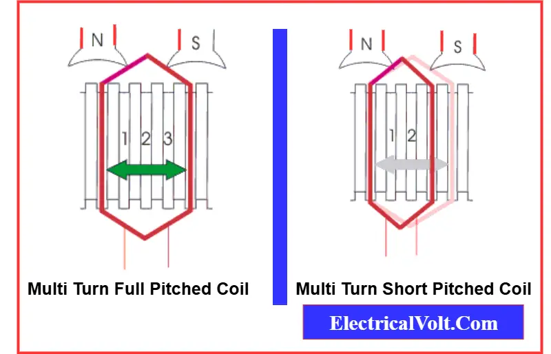
In a full-pitch coil, the emf induced in one side of the coil is displaced by 180° from the emf induced in the other side. As a result, the total terminal voltage of the coil is simply the arithmetic sum of the two emfs.
However, if the coil span is shorter than the pole pitch, the winding is called a fractional-pitch coil. In this case, the phase difference between the induced emfs in the two sides is less than 180°. Therefore, the resultant terminal voltage of the coil becomes the vector sum of the two emfs, which is lower than that of a full-pitch coil.
In practice, a coil span as small as 0.8 of a pole pitch can be used without causing a significant reduction in the induced EMF. Fractional-pitch windings are commonly adopted to reduce copper usage in end connections and to enhance commutation performance.
Commutator Pitch
The commutator pitch is the distance between the two commutator segments to which the ends of the same armature coil are connected. It is expressed in terms of the number of commutator bars or segments.
Armature Conductors
Armature conductors are the individual wire segments placed in the slots of the armature core. These conductors are connected in series or parallel to form turns and coils, which together make up the complete armature winding.
When current flows through the armature conductors, they interact with the magnetic field of the field winding, producing torque in motors or induced voltage in generators. Proper arrangement and connection of the armature conductors are essential for efficient operation of electrical machines.
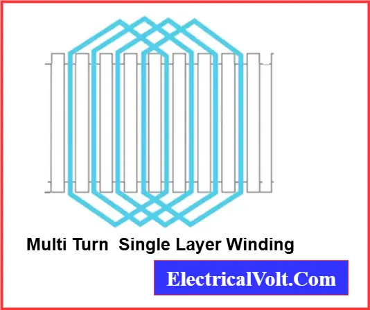
Single-Layer Armature Winding
In a single-layer winding, each slot of the armature contains only one side of a coil. In other words, one coil side is placed in each armature slot. This simple arrangement is known as single-layer armature winding.
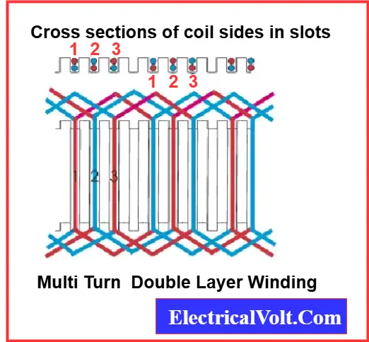
Double-Layer Armature Winding
In a double-layer winding, each armature slot accommodates two coil sides: one in the upper half and the other in the lower half of the slot. The coils are arranged so that if one side is placed in the upper half of a slot, the corresponding side of the same coil is placed in the lower half of another slot located one coil pitch away.
Summary: Single Layer Vs Double Layer Armature Winding
| Feature | Single-Layer Winding | Double-Layer Winding |
| Slots per coil side | 1 | 2 (upper & lower halves) |
| Complexity | Simple | Complex |
| Voltage & Current Handling | Moderate | High |
| Magnetic Flux Distribution | Less uniform | More uniform |
| Common Applications | Small DC motors | Medium & large DC machines |
| Insulation Requirement | Lower | Higher |
Armature Winding vs Field Winding
The armature winding and the field winding work together in electrical machines but serve different purposes. Here are the key differences:
Location:
- Armature Winding: Placed on the rotor (in DC machines) or stator (in AC machines).
- Field Winding: Placed on the poles of the machine (usually on the stator).
Function:
- Armature Winding: Induces voltage in generators and produces torque in motors.
- Field Winding: Produces the magnetic flux required for machine operation.
Current Type:
- Armature Winding: Carries AC (alternating current).
- Field Winding: Carries DC (direct current) in DC machines.
Both windings are essential for the operation of electrical machines. The armature winding interacts with the field winding flux to convert electrical energy to mechanical energy (in motors) or mechanical energy to electrical energy (in generators), making their coordination crucial for efficient machine performance.
Conclusion
Armature winding is a crucial part of electrical machines where voltage is induced in generators and torque is produced in motors. Along with the field winding, which creates the magnetic flux, it enables efficient energy conversion. T
The arrangement of turns, coils, and conductors in the armature plays a key role in machine performance. Understanding the meaning of armature winding, its difference from field winding, and the role of conductors and coils helps build a strong foundation in electrical machine concepts.
Frequently Asked Questions (FAQs)
Armature winding in a motor is the set of conductors placed in the armature core where current flows, producing torque that drives the motor.
The field winding produces the magnetic flux needed for machine operation. In DC machines, it is usually excited by a DC supply to create the magnetic field.
Armature winding is where voltage is induced or torque is produced, while field winding generates the magnetic flux. Together, they enable energy conversion in electrical machines.
Armature conductors are the individual wire segments placed in the slots of the armature core. When connected, they form turns and coils that carry current and interact with the magnetic field.
An armature coil consists of several turns of conductors connected in series. These coils are placed in the slots of the armature to form the complete armature winding.
Related Articles:
Great and useful info