This article describes various methods of Speed Control Methods of Induction Motor. An induction motor is a type of electric motor that runs on an alternating current supply. In general, an induction motor is considered a constant-speed motor, and controlling its speed is a challenging task. Also, the variation in the speed of the induction motor affects its efficiency and performance. Although, we can employ several methods that allow us to change the speed of an induction motor.
Table of Contents
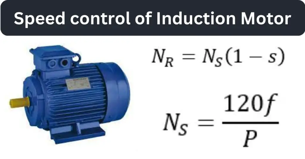
Speed of Induction Motor
In the case of induction motors, two speeds are relevant, namely, synchronous speed and rotor speed.
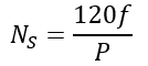
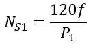
The synchronous speed is the speed of rotating magnetic flux in the air gap. It is denoted by NS and is given by,

Where f is the frequency of AC supply, and P is the number of magnetic poles in the stator winding.
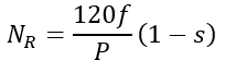
The speed of the rotor in an induction motor is always less than the synchronous speed and is denoted by NR. The rotor speed of an induction motor is given by,
Where “s” is the slip. The slip in an induction motor is the difference between synchronous speed and rotor speed.
The torque developed by the induction motor also plays a vital role in speed control. The following equation gives the torque developed by an induction motor.
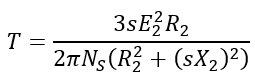
Where E2 is the rotor emf, R2 is the rotor circuit resistance, and X2 is the rotor reactance.
Speed Control Methods of Induction Motor
In an induction motor, we can control the speed of the motor through Speed Control Methods of Induction Motor. They both the stator side and the rotor side.
Some commonly used methods to control the speed of an induction motor are given below.
From the stator side, the Speed Control Method of 3 Phase Induction Motor:
- Voltage control method
- Frequency control method
- Stator pole change method
- V/f control method
From the rotor side, the speed control methods of the induction motor:
- Rotor resistance control method
- Slip Frequency EMF Injection Method
- Cascading connection method
Let us now discuss each of these methods in detail.
Induction Motor Speed Control Methods From Stator Side
(1). Voltage Control Method:
In the Induction Motor Speed Control Methods the voltage control method is the best, the supply voltage is changed with the help of a starter autotransformer.
According to the torque equation, we get
Under running conditions, the slip in the induction motor is very small. Thus, the term (sX2)2 can be neglected.
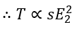
Also, we know that the rotor emf E2 is directly proportional to the stator voltage or supply voltage. Thus,
Hence, if we decrease the supply voltage, the torque will also decrease. For a given load, the slip will increase with the decrease in the supply voltage. To maintain the same load torque, the speed must decrease. This way, we can control the speed of an induction motor by changing the supply voltage.
However, we cannot reduce the supply voltage below a specific value. Otherwise, it will cause unstable motor operation.
This method is used when a minor variation in speed is required because this can damage the motor due to overheating.
The soft starters work on this principle for controlling the speed of the motor.
(2). Frequency Control Method:
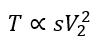
As we know, the speed of an induction motor depends upon the supply frequency, i.e.
The induction motor speed is given by,
Hence, the speed of an induction motor can be changed by changing the supply frequency. This method is rarely used. This is because, at low supply frequencies, the current drawn by the motor becomes too high due to a reduction in the inductive reactance. Also, the decrease in the supply frequency alone without changing voltage reduces the maximum torque developed by the motor.
(3). Stator Pole Change Method:
From the expression of synchronous speed, we can see,

Thus, we can change the speed of an induction motor by changing the number of stator poles. Two or more independent stator windings are wound in the same slots for different numbers of poles to achieve change in stator poles. This method is mainly used in squirrel cage induction motors.
The speed of the motor operating at 50 Hz for different poles is given below.
| Number of Poles | Speed of Motor |
| 2 | 3000 |
| 4 | 1500 |
| 6 | 1000 |
| 8 | 750 |
(4). V/f Control Method:
To control the speed of an induction motor, this is the most widely used method. In this method, the supply voltage and frequency are reduced or increased in the same proportion. Maintaining the ratio of voltage and frequency, the magnetic flux in the air gap of the motor remains constant. Also, due to the constant V/f, the torque developed by the motor is constant. When V/f control is used in fan and pump applications, it is possible to save energy.
This method provides higher efficiency during running conditions. This is called the variable voltage and variable frequency (VVVF) method. Using this method, we can control the speed of an induction motor over a wide range. You may have seen the VFDs, which function on this principle for controlling the motor’s speed.
Let us now discuss the methods of speed control from the rotor side of the induction motor.
Methods of Speed Control of Induction Motor From Rotor Side:
(5). Rotor Resistance Control Method:
In these Methods of Speed Control of Induction Motor, an external resistance is inserted in the rotor circuit of the induction motor. However, this method can be used for slip-ring induction motors only.
According to the torque equation, we get,

Under running conditions, the term (sX2)2 is very small and thus can be neglected.

Hence, if the rotor resistance R2 increases, the torque will decrease, but to maintain the load torque constant, the slip must increase. This will take place by decreasing the rotor speed.
This way, adding an external resistance to the rotor circuit of the induction motor decreases the motor speed.
The key benefit of this method is that it increases the starting torque of the motor. However, it results in inefficiency due to high slip and copper loss.
(6). Slip Frequency EMF Injection into Rotor Circuit Method:
In this Method of Speed Control of Induction Motor, the speed is changed by applying a voltage to the rotor circuit. The most important thing that has to be considered is that the frequency of the applied voltage must be equal to the slip frequency.
If the applied voltage or emf has an opposite phase concerning the rotor voltage or emf, the rotor resistance will increase. On the other hand, if the applied voltage has the same phase as the rotor emf, the rotor resistance will decrease.
Hence, by changing the phase of the applied voltage to the rotor, we can change the rotor circuit resistance and, hence, the speed of the motor.
The significant benefit of this method is that it provides a wide range of speed control.
(7). Cascading Connection Method:
In the cascading Methods of Speed Control of 3 Phase Induction Motor, two induction motors are connected and run at the same speed. Here, one induction motor is supplied from a 3-phase supply, and the second motor is powered from the induced voltage in the first motor with the help of slip rings.
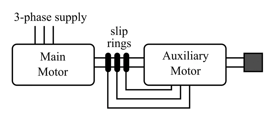
The motor directly excited from the 3-phase supply is termed the main motor, and the motor excited from the induced EMF or voltage is referred to as the auxiliary motor.
Let,
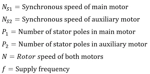
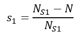
Therefore, the slip in the main motor is given by,
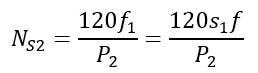
The frequency of induced emf in the rotor is,

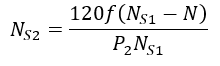
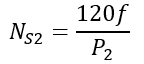
Since the auxiliary motor is supplied from the induced emf in the main motor. Thus, the synchronous speed of the auxiliary motor is given by,
Also,
Under the no-load conditions, the rotor speed of the auxiliary motor is approximately equal to its synchronous speed, i.e.,
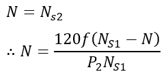
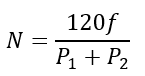
On rearranging this equation, we get,
Now, according to this equation of induction motor speed, the following four cases are possible.
Case I – When the main induction motor is working:
Case II – When the auxiliary induction motor is working:
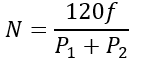
Case III – When cumulative cascading is done, the speed of two motors is:
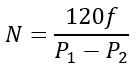
Case IV – When differential cascading is done, the speed of two motors is:
Conclusion
In conclusion, the Speed Control Method of Induction Motor can be changed by using any of the methods mentioned above. In general, the induction motors are considered to have a constant speed. But, by employing any of the above-given methods, we can control the speed. Different methods have different benefits and drawbacks.