This article describes the difference between RS485. The RS232 and RS485 are serial interface standards used for data communication. When the data is communicated between two nodes, it is difficult to have smooth data transfer due to some reasons like noise, ground level differences, mismatch of impedance, etc. So, organizations like
Electronic Industry Association (EIA) and Telecommunication Industries Association (TIA) have set up standards for the production of cables and other tools which are used to set up a network.
By this, compatibility between devices manufactured by different manufacturers is ensured. Also, better and smooth transfer of data over long routes is achieved. These standards also improve data rates.
The RS232 and RS485 are standards for data cables and are used for serial communication. RS prefix had been suggested by EIA, it means Recommended Standards. They are serial interfaces that specify the transmission media and have a predefined set of logic levels, data rates, and timings.
They exchange data between two nodes on a network. For this purpose, the most commonly used tools are line drivers and receivers. Both RS232 and RS485 are one of the oldest serial interfaces. They are very widely used in control and measurement equipment due to their simplicity and low cost.
The transfer of data is classified as:
- Single-ended
- Differential
Almost all serial devices make use of the Universal Asynchronous Receiver Transmitter (UART) integrated circuits for the implementation of a communication protocol. UART protocol can transmit data in portions. UART is generally transferred in 8 bits and is defined along with particular start bits, stop bits, and parity bits at a specific data rate.
Baud Rate: the rate at which information is transferred in a communication channel is called the baud rate.
RS 232
The RS 232 is meant for single-ended communication. In a RS 232, the transmitter wire (TX) of device 1 and the receiver wire (RX) of device 2 are connected. Both these connections are single-ended with reference ground. Single-ended means that the voltage is measured with reference to the ground.
In the standard, it is recommended that the voltage must be between +12 V and -12 V. The signals with voltage levels degraded to as low as 3V can be understood. The cable used to connect Device 1 and Device 2 can be made from parallel wires or twisted pair cables. The cable has 9 wires and in some connectors, 25 wires are used. In this, each wire has some particular role in data transmission.
RS 232 supports full duplex transmission, which means it can transmit data in both directions- sending and receiving. It should generally be within 50 ft (15m). The data is transmitted in ASCII characters. RS 232 provides a baud rate of up to 20k bits per second.
Advantages of RS 232
The advantages of RS 232 are:
- RS 232 is the most widely used communication protocol.
- It has low complexity.
- RS 232 also supports full duplex communication.
Disadvantages of RS232
The disadvantages of RS 232 are:
- RS 232 supports communication between only two devices.
- RS 232 can work only over short distances.
- RS 232 is relatively more susceptible to noise.
RS485
The RS 485 supports differential signaling on two lines of communication. On one RS 485 bus, a maximum of 32 devices can be connected. But only one device can communicate at a time (half duplex). The cable has three wires – two are for data transmission and one is for ground. In this standard it is specified, voltages between +5V and -5 V are used. RS 485 provides the common mode noise rejection also because of the differential format. The maximum cable length is 4000 ft (1200 m). The data is transferred at a 10 Mbps baud rate.
Advantages of RS485
The advantages of RS 485 are:
- RS 485 can support many devices on the same bus.
- RS 485 is less susceptible to noise as compared to RS 232.
- RS 485 works over longer distances.
- RS 485 has a higher baud rate.
Disadvantages of RS485
The disadvantages of RS 485 are:
- RS 485 is used relatively less than RS 232.
- RS 485 needs termination resistors.
- RS 485 can only support half-duplex communication.
Difference between RS232 and RS485
| SPECIFICATIONS | RS232 | RS485 |
| Mode of operation | RS 232 is single ended. | RS 485 is differential. |
| Number of devices that can be connected | Only two devices can be connected. | Here, a maximum of 32 devices can be connected. |
| Maximum cable length allowed | 15 feet | 4000 feet |
| Baud rate | 20 kbps | 10 Mbps |
| Voltage of Driver Output | ±25 V | -7 V to +12 V |
| Logic levels | ±5 V to ±15 V | ±1.5 V to ±6 V |
| Maximum receiver input impedance | 3 to 7 W | 12 W |
| Receiver sensitivity | ±3 V | ±200 mV |
Connector used for RS232 and RS485
The serial communication protocols RS 232 and RS 485 use a connector to connect with different devices. This connector is generally 9 pin connector called the DB9 connector. In some cases, it is having 25 pins.
Connector for RS232
The DB9 means D-sub miniature connector plug having 9 pins. Each pin has a different function. The pinout diagram of the D89 connector is shown below.
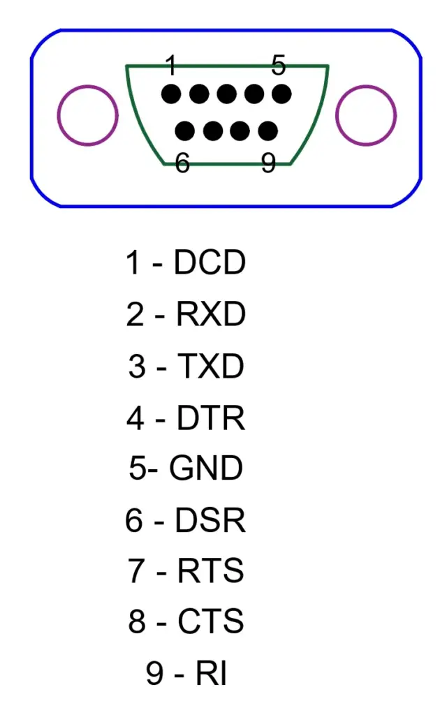
The functions of different pins are:
PIN 1- Data Carrier Detect (DCD)
After the detection of the data terminal, a signal will be sent from this pin to the data set which is going to be transmitted to the terminal.
PIN 2- Received Data (RXD):
The data set will receive an initial signal through the receive data line (RXD).
PIN 3- Transmitted Data (TXD):
The data terminal will receive a signal from the data set and a confirmation stating there is a connection between the data terminal and the data set.
PIN 4- Data Terminal Ready (DTR):
At this terminal, a positive voltage is applied which is a sign that the data terminal is prepared for the transmission of data.
PIN 5- Signal Ground (GND):
This pin of the signal ground provides a return path for serial communications. Without the signal ground, serial data cannot be transmitted between devices. It is a return for all signals on a single interface.
PIN 6- Data Set Ready (DSR):
At this pin, a positive voltage is applied which will ensure that serial communication between a data terminal and a data set could be accomplished.
PIN 7- Request To Send (RTS):
A positive voltage at this terminal will indicate the request to send can be performed. This means that the data set is able to send information to the data terminal without any interference.
PIN 8- Clear to Send (CS):
After the establishment of the connections between a data terminal and a distant modem, a clear-to-send signal (CS) will ensure that the data terminal recognizes that communications can be performed.
PIN 9- Ring Indicator (RI):
This signal will be activated when the modem working as a data set detects low frequency. If this occurs, the data terminal is alerted. But the RI would not stop the flow of serial data between devices.
Connector for RS485
The pinout diagram of the RS485 connector is shown below.
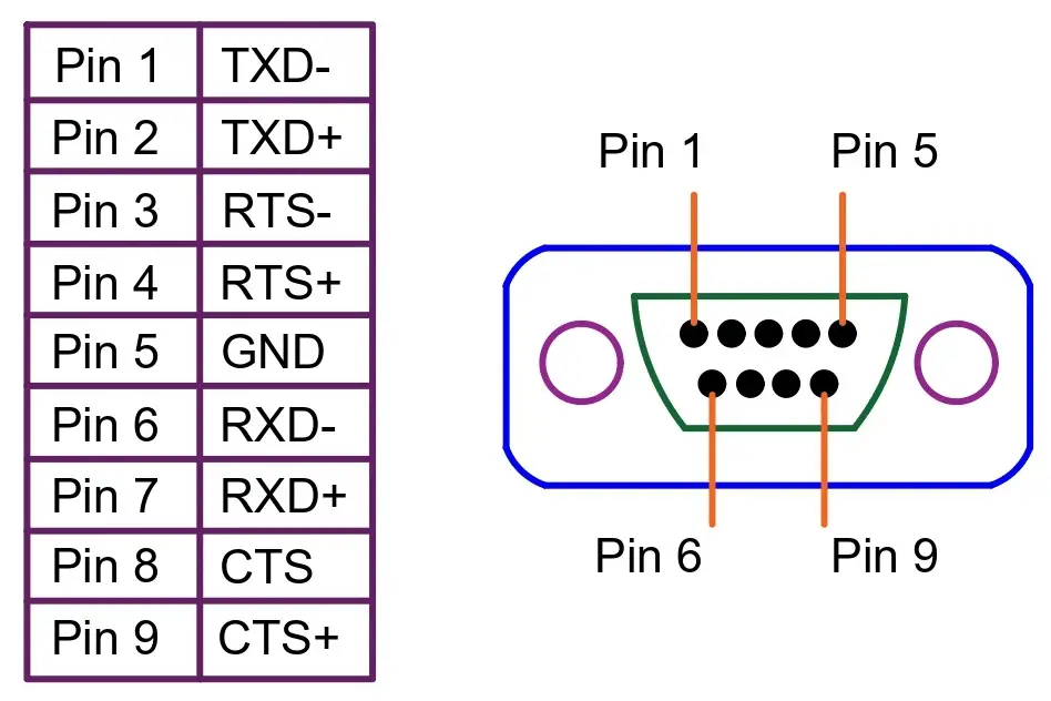
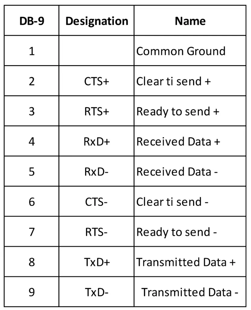
The functions of different pins are:
Pin 1 and Pin 2: TXD- and TXD+
These lines carry the actual transmitted data.
Pin 3 and Pin 4: RTS- and RTS+
This signal is activated when the device is ready to send.
Pin 5: Ground
This pin connects to the ground, which means that it gives a shared path for returning the electrical circuit.
Pin 6 and Pin 7: RXD- and RXD+
These lines are used for data transmission between two devices.
Pin 8 and Pin 9: CTS- and CTS+
It is clear to send a signal which is sent after a connection is established between two devices. This signal provides confirmation for the recognition of the device.