An ideal transformer has zero winding resistance, but the primary and secondary winding of the transformer has a certain resistance. In this article, we will discuss transformer winding resistance and its calculation.
Transformer winding is made of copper or aluminum, and the resistivity of copper and aluminum is 1.68 x 10⁻⁸ Ω-m and 2.65 x 10⁻⁸ Ω-m respectively. The transformer winding is made of many turns therefore copper or aluminum is used in meters.
The resistance of the conductor is proportional to the length of the wire, and resistivity, and inversely proportional to the cross-section area. Therefore, the primary and the secondary winding of the transformer have finite resistance. In an ideal transformer winding resistance is considered zero which is totally hypothetical.
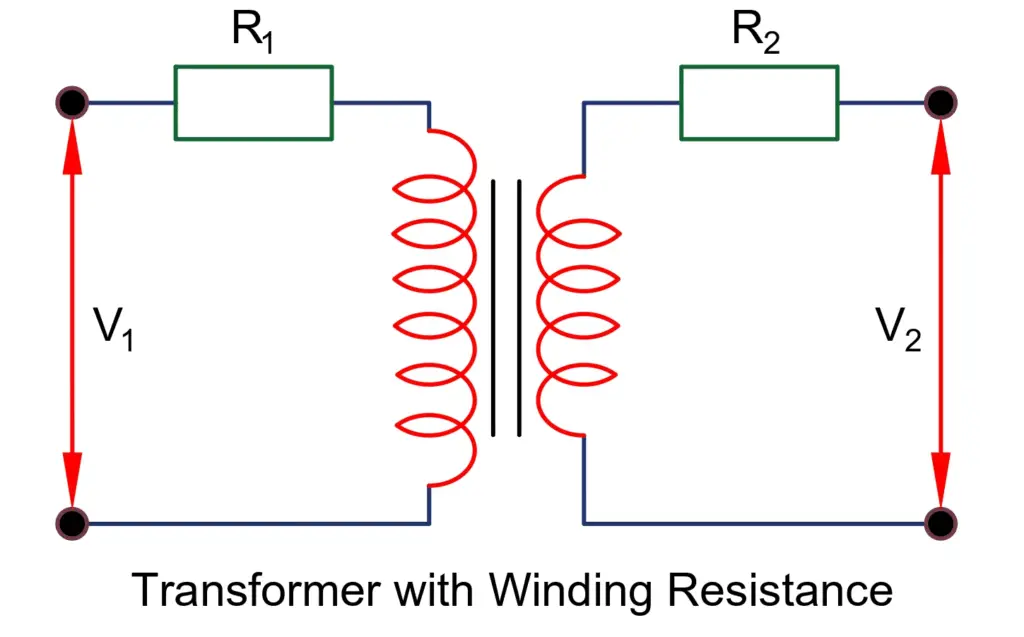
The voltage drop in the transformer is caused by the voltage drop in resistance and reactance of the transformer. In this section, we are considering only the resistance calculation of the transformer. The resistance of the primary and secondary winding is shown below;
The winding resistance can be transferred from primary to secondary or vice versa. The voltage drop remains the same either the primary resistance is transferred to the secondary side or the secondary side resistance is transferred to the primary side. When the transformer resistance is referred to one side of the transformer, the calculation of resistance and reactance of the transformer becomes very easy.
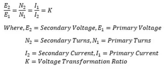
Before knowing how to transfer the resistance from primary to secondary or vice versa, it is essential to understand the voltage transformation ratio of the transformer. The voltage transformation ratio of the transformer is denoted by the letter “K’.
Case1:
Transformer equivalent resistance when secondary resistance transferred to the primary side
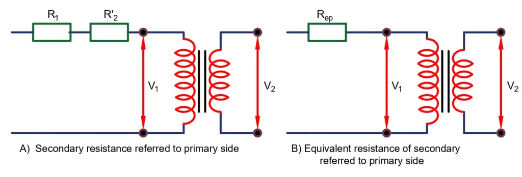
Let the R1 and R2 be the resistance of the transformer’s primary and secondary winding, and I1 and I2 be the primary and secondary currents. R’2 is the equivalent resistance of the secondary referred to the primary side.
When the secondary resistance is referred to as primary, the transformer performance parameter like voltage regulation and losses remain the same. The copper loss in secondary winding when I2 current flows through it is given as;
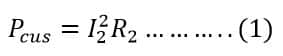
Now, if secondary resistance is referred to the primary side, the copper loss in primary due to R2‘ is;
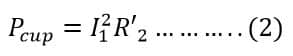
The copper loss calculated in equation(1) and(2) is equal, so
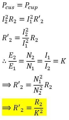
Thus, the total resistance referred to the primary side is;
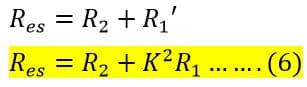
Case2:
Transformer equivalent resistance when primary resistance is transferred to the secondary side
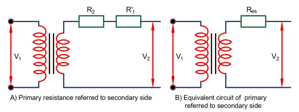
Let the R1 and R2 be the resistance of the transformer’s primary and secondary winding. I1 and I2 are the primary and secondary currents. R’2 is the equivalent resistance of the secondary referred to the primary side.
When the secondary resistance is referred to the primary side, the transformer performance parameter like voltage regulation and losses remain the same. The copper loss in secondary winding when I2 current flows through it is given as;
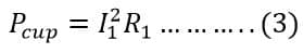
Now, if the primary resistance is referred to the secondary side, the copper loss in the secondary due to R1‘ is
The copper loss calculated in equation(4) and (5) is equal,
Thus, the total resistance referred to the secondary side is;