This article describes a comprehensive explanation of various terms which are commonly used in the SIL verification process.
For Safety Instrumented Systems (SIS) in the process industries, two IEC standards are applicable, namely IEC 61508 and IEC 61511. For manufacturers of devices that are used in safety instrumented systems (for example logic solvers, and transmitters), IEC 61508 is applicable. For end users that would implement a Safety instrumented System (for example a chemical plant that uses an SIS), IEC 61511 is applicable.
According to IEC 61511, SIL verification is a crucial part of the safety life cycle, taking place during phase 4 (SIS design and engineering) after the completion of hazard and risk analysis, allocation of safety functions to protection layers, and SIS safety requirement specification.
Let us start with Safety and Functional Safety.
What is safety? It is freedom from unacceptable risk
Safety refers to the state or quality of being safe, protected, or without risk of harm. It encompasses a wider range of concepts including physical safety, health and welfare, and environmental safety.
Functional Safety: part of safety that depends on safety functions implemented in a safety system
Functional safety, on the other hand, refers to the safety related to the specific functions performed by safety-related systems, such as emergency stops, protection against fire and explosion, and protection of personnel and the environment. It involves ensuring that these systems operate as intended and do not cause harm in the event of failure.
functional safety is a subset of safety that focuses on the design and operation of safety-related systems, while safety encompasses all aspects of ensuring a safe environment.
The characteristics of safety systems like ESD / SIS: It is Independent, it has a predetermined safe state, and it works only when the process runs out of control.
SIL (Safety Integrity Level)
It represents a quantifiable target that measures the safety level of a process. Determining a target SIL level must be based on evaluating the likelihood of an incident occurring and the impact of such an incident.
HFT (Hardware Fault Tolerance)
It refers to the capability of the equipment to continue performing its required function despite faults or errors.
The HFT of a device is a reflection of the quality of its safety system.
For instance, HFT of N means that N+1 faults can result in the loss of the entire safety function.
On the other hand, HFT-0 means that a single fault can lead to the loss of the entire safety function (e.g., a 1oo1 pressure transmitter used in a SIF). The failure of this transmitter will result in the loss of the entire safety loop.
HFT-1 indicates that two faults are needed to cause the loss of the entire safety function (e.g., 1oo2 voting).
The following table illustrates the HFT levels associated with various voting configurations:
Table 1: HFT and Voting Configuration Correlation
| Hardware Fault Tolerance | Voting Configurations |
| 0 | 1oo1, 2oo2 |
| 1 | 1oo2, 2oo3 |
| 2 | 1oo3, 2oo4 |
It is important to note that HFT is not equivalent to the presence of redundant devices. For example, the 2oo2 configuration is redundant but fault-tolerant. A higher HFT number contributes to a higher SIL level of equipment.
SFF (Safe Failure Function)
It is a measure of the effectiveness of the built-in diagnosis of a device. Any failure that occurs can be classified into two types: safe failure (λS) and dangerous failure (λD). The failure can be detected through diagnosis or remain undetected, with the latter being the most concerning (as it is neither safe nor detected by any means of diagnosis). The safe failure fraction is calculated as the ratio of the sum of safe failures (λs = λSD + λSU) and dangerous detected failures (λDU) to the total number of failures.
The higher the SFF, the more comprehensive the built-in diagnostic coverage of the device, allowing for a reasonably high SIL level to be claimed.
Architectural constraints refer to restrictions on the hardware selected to execute a safety instrumented function, regardless of the subsystem performance (such as PFDavg).
Table 2: Architectural constraints for type A subsystems – Route 1H
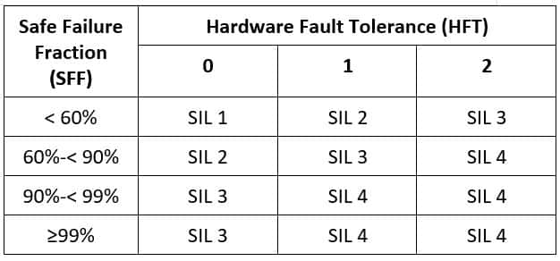
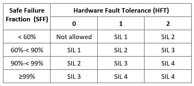
Table 3: Architectural constraints for type B subsystems – Route 1H
Type A devices are considered simple and have well-known failure modes, such as valves, relays, RTDs, thermocouples, solenoids, and limit switches.
Type B devices, on the other hand, are more complex and have unknown failure modes. Any device with a microprocessor is considered Type B, including smart transmitters, valve positioners, programmable logic controllers (PLCs), distributed control systems (DCSs), and machine monitoring systems (MMSs).
Hardware fault tolerance – Table in IEC 61508 Route 2H
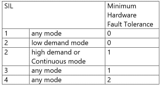
Table 6 in IEC 61511 is the same as the table for IEC 65108- Route 2H.
e.g. for any given mode for achieving SIL3 for a SIF, we require HFT as 1. Hence without redundant devices/final elements required SIL for SIF will not be achieved.
As we saw above, IEC 61508 gives us two options, called Route 1H and Route 2H.
Route 1H: The Hardware Fault Tolerance is based on the Type [A or B], the Safe Failure Fraction, and the SIL.
Route 2H: The Hardware Fault Tolerance is based on Proven Use data and the SIL.
PFDavg (Average Probability of Failure on Demand) is a metric used to calculate the likelihood of a system failing dangerously and unable to perform its safety function when required. IEC 61508 and IEC 61511 use PFDavg to define the SIL rating. The PFDavg increases by an order of magnitude with each increase in SIL rating.
Table 4: SIL and PFDavg correlation for low-demand mode
| Safety Integrity Level | PFDavg Low Demand Mode of Operation |
| 4 | >10-5 to <10-4 |
| 3 | >10-4 to <10–3 |
| 2 | >10-3 to <10-2 |
| 1 | >10-2 to <10-1 |
Let’s examine a specific example of a pressure transmitter’s SIL certificate (Yokogawa make Pressure Transmitter EJA series) to better understand the terms discussed earlier:
Link to the certificate: https://web-material3.yokogawa.com/EJA-E_Series_SIL_Certificate.us.pdf
The device is classified as a Type B device.
When HFT is 0 (1oo1), the SIL rating is 2.
When HFT is 1 (1oo2), the SIL rating is 3.
The Safe Failure Fraction (SFF), as stated on page 2 of the certificate, is calculated as (0 + 54 + 331) / (0 + 54 + 331 + 39) = 90.8%.
According to the information in Table 3, if the SFF is greater than 90% and the HFT is 0 (1oo1, 2oo2), then the architecture constraints allow for a SIL 2 rating to be claimed.
Even with the 2oo2 redundant configuration, the highest SIL rating that can be achieved is still SIL 2. The level of redundancy does not automatically equate to a higher SIL rating; it must be evaluated in conjunction with the HFT level.
Based on Table 3, if the SFF is greater than 90% and the HFT is 1 (1oo2), then the architecture constraints permit a SIL 3 rating to be claimed.
SIL Verification and SIL Validation are two distinct steps in the process of ensuring functional safety in industrial automation systems.
SIL Verification is the process of checking that the design and implementation of a safety instrumented system (SIS) meet the requirements specified in functional safety standards such as IEC 61508 or IEC 61511. This includes reviewing the design documentation, testing the components and systems, and ensuring that the design and implementation are in accordance with the standards.
SIL Validation, on the other hand, is the process of demonstrating that the SIS will perform its intended safety function during normal and abnormal conditions. This is typically done through simulations, testing, and/or analysis. The aim of SIL Validation is to demonstrate that the SIS will reliably perform its safety function when required and that the overall safety integrity level (SIL) of the system is adequate.
In summary, SIL Verification focuses on checking the design and implementation of the SIS, while SIL Validation focuses on demonstrating the performance of the SIS under normal and abnormal conditions.
Proof Test Interval: Refers to the frequency with which a safety instrumented system or its components undergo a formal test to verify its operability and proper functioning. The goal is to detect any defects before they can cause a dangerous failure.
MTTR (Mean Time to Restoration): The average time required to identify and repair a failed component or system and put it back into operation.
MTBF (Mean Time Between Failures): The average time between system failures.
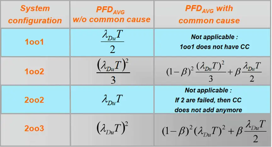
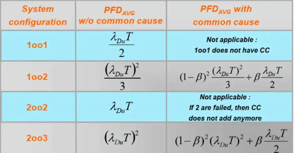
Beta: Common cause of failure rate, which refers to the probability that multiple safety-critical components will fail simultaneously.
It is a percentage of the failure rate.
SIL (Safety Integrity Level): A measure of the level of safety provided by a safety instrumented system, defined in terms of the average probability of failure on demand (PFDavg). It is used to rank the safety requirements of a system and the necessary measures to achieve them.
PFDavg (Average Probability of Failure on Demand): The average probability that a safety instrumented system will fail to perform its safety function when required. It is used to determine the required SIL level for a given safety application.
RRF (Risk reduction Factor) = 1/PFD. With reference to Table 4 above, if an SIF requires a risk reduction of 125, that means that an SIF should be SIL2 in low-demand mode. If a SIF requires a risk reduction of 1025, that means that an SIF should be SIL3 in low-demand mode.
There are 2 ways to reduce the risk reduce the frequency and reduce consequences. Most typically safety systems reduce the frequency.
What is a demand? It is a process request for protective action, for example, a high or low trip.
Main difference between a control system (DCS) and a safety system (ESD / SIS)?
The control system is 24/7 in control, The Safety system only acts on demand = standby or sleeping
| DCS | SIS |
| Always in “active” mode, the plant cannot run if it is not running | Normally in “passive” mode, it acts only in case of an emergency |
| The health of the system is always evident | One has to periodically test to know the health of the system |
| May or may not have redundant components | Generally has redundant components, could be. even triple or quad-redundant |
| Need not to be designed as per IEC 61508 standard | Generally designed as per IEC 61508 standard to ensure very high availability and reliability. |
| System failure results in downtime and production | System failure can result In a catastrophe and loss of assets, people, and environmental damage |
| Failures are detected easily since the system is running 24/7 | Failure may remain undetected |
| No guarantee on the state of outputs during the failure of the control system, most likely outputs are on hold | Predictable state of output on any revealed failure in the system, Fail-safe design |
| High flexibility needed to develop and maintain (complex) control and automation applications | Fixed functionality, carefully minimized during design |
| Improvements or changes in the configuration but also repairs are mainly implemented online. | No modification of safeguarding functionality in a running plant Rigid procedures to make any change |
What’s better for safety, 1oo2 or 2oo2?
1oo2 is better for safety, 2oo2 is better for availability
What’s the purpose of 2oo3?
2oo3 is a good combination for better safety and higher availability
What do you mean by sensor validation?
Sensor validation means you have more than one sensor and the values from the sensors are compared. If the values from the sensors differ too much an action/alarm can be raised.
What is the process safety time?
Process Safety Time is the time left between demand and the completion of the actions before things go wrong. For example, a high level in a vessel is measured, this means that there are 15 minutes left to close the pipes before the vessel starts overflowing.
What is the effect of overrides on the SIF?
Overrides “kill” the safety function. The intention of the SIF is bypassed, so demand cannot result in a corrective action anymore.
How do we deal with overrides?
A hardwired enable key switch is highly recommended. With strict procedures (permits) and indications that overrides are placed in the system.
What is Systematic Capability?
Systematic Capability is a measure (expressed on a scale from SC 1 to SC4) of the confidence that the systematic safety integrity of an element, meets the requirements of the specified SIL, in respect of the specified element safety function.
In other words, systematic capability is the quality of avoiding systematic failures (by having Functional safety management in place)
Let’s have a detailed case study.
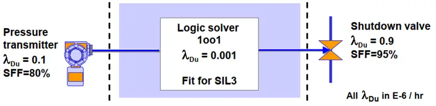
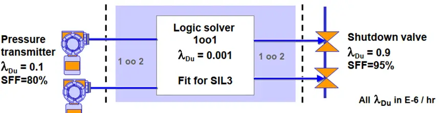
A customer asks for a HIPPS with pressure measuring and shut down the valve with SIL 3. He will use the following elements (sub-systems)
sensor: transmitter make X, IEC 61508 type B, SFF=80%
logic solver: make Honeywell, Safety Manager, SIL3
final element: Pneumatic shut down valve make Z,
IEC 61508 type A, SFF=96%
What is the configuration of the system if the customer asks for
1. compliance with IEC 61508 Route 1H
2. compliance with IEC 61508 Route 2H
3. compliance with IEC 61511
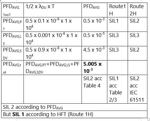
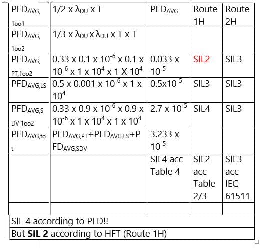
Consider 1 year = 10000 hours as proof test interval for simple calculation. Consider the calculation without common causes.
SIL Verification Factors
SIL Verification has three factors that have to be checked
1. PFDavg
value of the Safety Function. This may be implemented by a closed loop consisting of sensors, logic solvers, and final elements.
2. Systematic Capability
The elements and devices/ subsystems in the SIF must be capable to meet the target SIL. Thus these devices should preferably be certified by third parties for compliance with
the IEC 61508 standard. Or one can go with a “proven in use” justification.
3. Architectural Constraints
The design of the SIF must comply with certain architectural constraints. We have to refer to certain tables in the standards that set the minimum parameters such as Hardware Fault Tolerance for these designs.
- Achieving a better SIL level for a Safety Instrumented Function (SIF) device can be accomplished by having a lower PFDavg value, a higher SFF value (>90%), and a higher HFT level.
- PFDavg is an important factor, but not the only one for the determination of the SIL. There are two other criteria, namely Systematic Capability and Architectural Constraints that have to be considered for the loop.
- Merely having a piece of equipment certified for use in SIL 2 applications does not guarantee that the entire SIF or loop will meet the SIL 2 requirements. A comprehensive analysis of all SIF components (sensors, logic solvers, and final elements) must be performed according to the latest standards.
- Improving the PFDavg value can be achieved by reducing the testing interval (increasing the testing frequency) and implementing partial stroke testing.
- During the SIL verification process, the SIL certificate and safety manuals for SIF components must be made readily available.
- Where possible, conservative failure rate data should be used, such as industry databases like OREDA and SINTEF/exida SERH, as the data provided in the SIL certificate can sometimes be overly optimistic.
- Users are advised to familiarize themselves with the various definitions, competency requirements, and guidelines stated in IEC 61508, IEC 61511, and ISA 84 before embarking on SIL verification activities.
Read Next: