Surge impedance loading is very important for knowing the maximum loading capacity of the transmission line. However, it is important to know the surge impedance before knowing the surge impedance loading.
We know that a long transmission line has distributed inductance and capacitance. It is the inherent property of a long transmission line.
Surge Impedance is the characteristic impedance of a lossless Transmission Line. As it is not involved with the load impedance, it is also called the Natural Impedance. When the line is assumed to be lossless, it means that the series resistance and shunt conductance is negligible i.e zero for power lines.
Therefore, we can say:
Shunt Conductance (G) = 0 and Series Resistance (R) = 0
Capacitive VAR = Inductive VAR
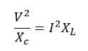
Where,
V = Phase voltage
I = Line Current
Xc = Capacitive reactance /phase
XL = Inductive reactance / phase
Upon simplifying Characteristic Impedance of a line can be represented as:
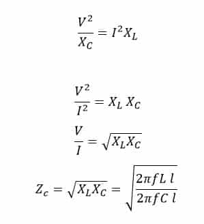
where,
f = Frequency of the system
l = Length of the line
L = Inductance per unit length of the line
C = Capacitance per unit length of the line
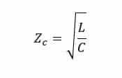
Zc is the surge impedance.
We can derive the surge impedance formula in the following way as well.
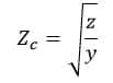
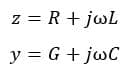
where ‘z’ is the series impedance per unit length per phase and ‘y’ is the shunt admittance per unit per length per phase. We can represent the z & y with the following expression.
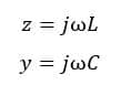
For lossless line
R=0
G=0
Now, for the lossless line, we can represent z and y as below,
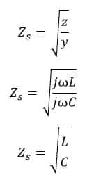
Hence, according to the definition of surge impedance,
Now we can say that a low surge impedance will help in dampening the amplitude of the surge voltage and therefore the stresses on the windings. Whereas, a low surge frequency fs will help in reducing the number of restrikes of the interrupter and as well as the steepness of the surge. Therefore, a low surge impedance and low surge frequency are always desirable.
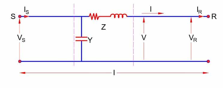
Voltage & Current Equation of Transmission Line
Surge Impedance Loading is the loading on the line whenever the load impedance matches exactly with that of the surge impedance of the transmission line. The surge impedance loading can also be referred to as the Characteristic Impedance Loading or the ideal loading or the ideal power transfer capability. Therefore, at SIL the load impedance is equal to the characteristic impedance.
Loading of any transmission line generally depends on some factors like Thermal Limitation, Voltage Regulation, and Stability limitation. It is due to these limitations of loading on the transmission line network, Surge Impedance Loading (SIL) is an important parameter in electrical science to predict the maximum loading capacity of any transmission line. It can be said that it is the maximum MW loading of the transmission line at which reactive power balance occurs.
Now if we assume a transmission line terminated with a load equal to the surge impedance of the line, let us look at the voltage profile along the line for surge impedance loading condition.
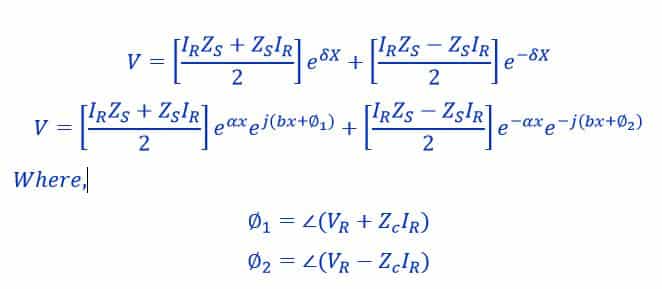
We know that the voltage & current at any point is given as
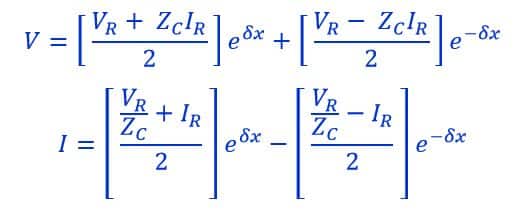
Where,
V and I = Voltage and Current at point x
VR and IR = Voltage and Current at receiving end
Zc = Characteristic Impedance
δ = Propagation Constant
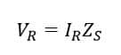
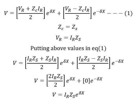
In the above equation, Zc is the characteristic impedance of the line. But as we here have assumed the line to be lossless, therefore characteristic impedance and surge impedance will be equal i.e Zc = Zs. And as the line is terminated with surge impedance, therefore ;
After substituting Vr in the V equation we get as below:
Propagation constant
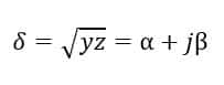
z = Series impedance per unit length per phase
y = Shunt admittance per unit length per phase
Putting the value of δ in the above equation of voltage we get
Surge Impedance Loading
The above voltage expression shows that the voltage profile along the line is uniform or flat for surge impedance loading. The unit of SIL is Watt or MW. This means the receiving end voltages and sending end voltages are the same for surge impedance loading.
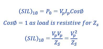
If Po is its natural load of the lines, (SIL)1∅ of the line per phase Surge impedance loading formula of single-phase circuit in watt is;
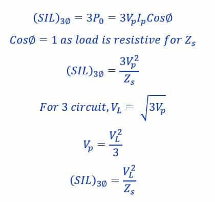
Surge impedance loading formula of three-phase circuit in watt,
Therefore, we can define Surge Impedance Loading also as the connected load in the transmission line for which the reactive generated is equal to the reactive power consumed which implies the flow of reactive power is zero which showcases the exact balance between reactive power generation and consumption.
Now as a fact loading consists of series inductance and shunt capacitance of lines. So here reactive power is consumed by series inductance and supplied by shunt capacitance of the line. Now depending on loading and SIL, a transmission line can act differently in different cases.
Interpretation of SIL
Case1: If Loading is equal to SIL
- Both Load Impedance and Characteristic Impedance are equal
- The transmission line can neither act as a source nor sink of reactive power
- Voltages of both sending end and receiving end are equal.
- Currents of both sending and receiving ends are equal.
- The power factor at both ends are unity
Case2: If Loading is greater than SIL
- Characteristic impedance is more than the Load Impedance
- The transmission line acts as the sink of reactive power.
- Sending end voltage is greater compared to receiving end voltage.
- Sending end current is lesser compared to receiving end current.
- Receiving end power factor stays at unity but sending end power factor is lagging.
Case3: If Loading is less than SIL
- Characteristic impedance is lesser compared to Load Impedance
- The transmission line acts as a reactive power source.
- The receiving end voltage is greater compared to sending end voltage.
- The current at the receiving end is less than the current at the sending end.
- The power factor at the receiving end stays at unity but the power factor at the sending end is leading.
Solved problems on surge impedance loading
Problem No.1
3 Phase 400 KV, 50 Hz, 300 km long lossless transmission line has a series
impedance Z = 0.3 Ω / km and a shunt admittance of Y = 3.75×10 -6 S / km.
Find
a) Surge impedance
b) Propagation constant
c) Surge impedance loading(SIL)
Solution:
Given,
3 phase, 400 KV, 50 Hz Line
Length = 300 km (lossless line)
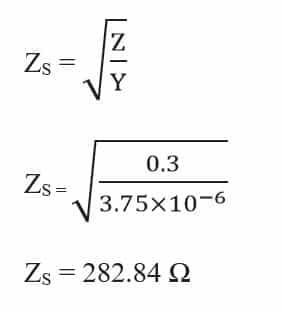
Z = 0.3 Ω / km
Y =3.75×10 -6 S / km
a) Surge impedance
b) Propagation constant
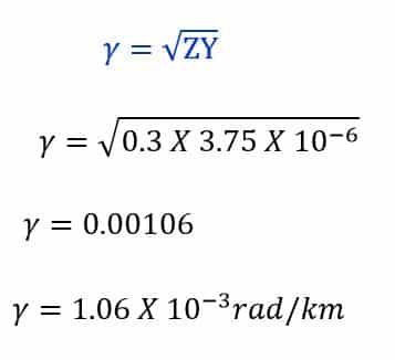
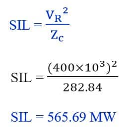
c) Surge impedance loading(SIL)
Problem No.2
The capacitance and inductance of a 400 kV, three-phase, 50 Hz Lossless transmission line are 10 nF/km/phase and 1.6 mH/km/phase respectively. The sending end voltage is operating at 400 kV. At the receiving end, it is required to maintain voltage at 400kV, when the line is delivering a 300MW load, What type of shunt compensation is required?
- Inductive
- Capacitive
- Zero
- Resistive
Solution:
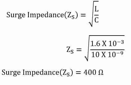
Surge Impedance is:
Now from the surge impedance loading formula:
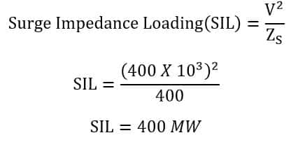
We can observe here that the load is lesser than the Surge Impedance Loading. Therefore, the shunt inductance is required in order to maintain the rated voltage at the receiving end.

Read Next: