Installation of a Partial Stroke Testing Device (PSD )in SIS Final Control Element for automated ON-OFF valve operation improves the Proof test requirement. Here, SIS is an abbreviated form of Safety Instrumented System.
Why do we need to do Partial Stroke Test (PST)?
In process plants, there are certain critical ON-OFF valves that either remain open or close. These valves are only operated during emergency situations or during plant shutdown. During normal operation, these valves should not be operated. But as an Instrumentation engineer, we need to do Preventive Maintenance of every instrument in the plant on regular basis. So now, in this case, we cannot do Preventive Maintenance of the valve.
So, in this case, we can use a Partial Stroke Testing Device to do the Partial Stroke Test of the ON-OFF valve. In Partial Stroke Test, the Partial Stroke Testing Device gives the command to operate the ON-OFF valve. The command operates the ON-OFF valve for a few percentages such that the operation of the valve does not have an adverse effect on the process. This action is done within a few seconds. The PSD records the data like command vs feedback, air supply pressure variations, diagnostic data, and many more depending upon the configuration.
The PSD is a positioner with some special functionality. Special configuration is required in the system to enable the Partial Stroke Test (PST) of any ON-OFF valve.
Benefits of Partial Stroke Test
- The diagnostics coverage for the Valve increases which helps in-
-Increase in the proof test frequency
-To reduce the probability of failure on demand of the valve
-Single valves instead of double valves can be used after proper calculations
-1 out of 2 configurations can be used instead of using higher configurations - PST helps to do Preventive Maintenance jobs on valves without taking the shutdown or isolating the line which involves various risks.
- Helps to achieve high overall safety due to better Safe Failure Fraction (SFF)
- Maintenance cost is reduced and human error is minimized.
Partial Stroke Testing Device(PSD)
Various design considerations are needed to be taken care of while designing the Partial Stroke Testing Device (PSD). Some of the important considerations are mentioned below for a valve with PSD.
- The technology of the Valve and the desired valve’s configuration.
- Failure rates of the valve assembly.
- Diagnostic coverage of the components and the SFF with and without the use of PSD.
- The final element should close the gap in Safety Integrity Level.
- The desired target for the proof test interval should be achieved.
- Proposed test interval for the PST if PSD is used.
- Valve seat leakage class to be decided based on the process requirements.
- Confirmation is to be taken whether the PST will be allowed for the particular service and the line or not.
- Each component of the valve assembly is to be listed and their failure rates to be considered.
- For valves that do not operate for more than 6 months, PST with a proper PSD is necessary to check the functionality of all components.
Impact of Probability of Failure on Demand (PFD)
The probability of failure on demand of the valve comes down by using the PST for valves that have less frequency of operation. This is because the valve is being tested at fixed intervals. During this test, all the diagnostics data are captured by the PSD. If any issue is found then action can be taken immediately which decreases the Probability of Failure on Demand.
Let us see an example of a PSD for Metso Neles Valveguard
Metso Neles Valveguard (Partial Stroke Testing Device)
Below shown connections are required for doing a PST
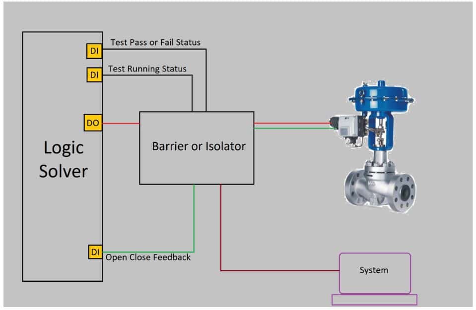
A logic solver is provided which is a type of block only in the DCS. Mainly 3 Digital Inputs are used. One input shows whether the test is running or not. Other shows the status of the test whether the test has passed or failed. While the 3rd one shows the positional feedback of the valve.
A digital output is used to operate the valve as per the command from the logic solver. Barriers or isolators as per the requirement of the system can be used for connecting the system cards to the field devices. An external system having a configuration tool is also connected for capturing all the data.