What is DeviceNet?
DeviceNet is an application layer communication protocol (layer 7 of the OSI model). It is used in the automation industry to connect and remotely manage a wide range of devices such as sensors and use CAN (Controller area network) technology.
What does DeviceNet offer?
- It provides a cost-effective solution for networking low-level units
- The ability to access low-level unit intelligence
- Point-to-point and master/slave capabilities
Main purposes of DeviceNet
- Transportation of the control-related information associated with low-level devices.
- Transportation of other information that is indirectly related to the controlled system, such as configuration parameters
DeviceNet Features
Summary of specific DeviceNet physical/media features:
- Configuration of Trunk line and/or drop lines
- Up to 64 nodes are supported
- Node removal without causing bus downtime
- Simultaneous support for bus-powered (sensors) and self-powered (actuators) units
- Use of sealed or bare connectors
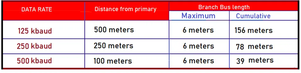
- Ability to select baud rate data: 125 k baud, 250 k baud, and 500 k baud
- Adjustable power supply configuration to meet individual application needs
- High current capability (up to 16 amps per power supply)
- Works with standard power supplies
- Sockets allow the connection of multiple power supplies from various compliant vendors to DeviceNet standards
- Integrated overload protection device
- Power supply available along the bus: main bus power and transmission circuits
Additional communication features provided by DeviceNet
- Use of Controller Area Network (CAN) technology for Media Control (MAC) and physical signaling.
- Connection-based modeling to facilitate communication between applications planned for efficient transfer of I/O data.
- Fragmentation for transfer of large blocks of information Duplication of MAC ID detection.
DeviceNet Topology
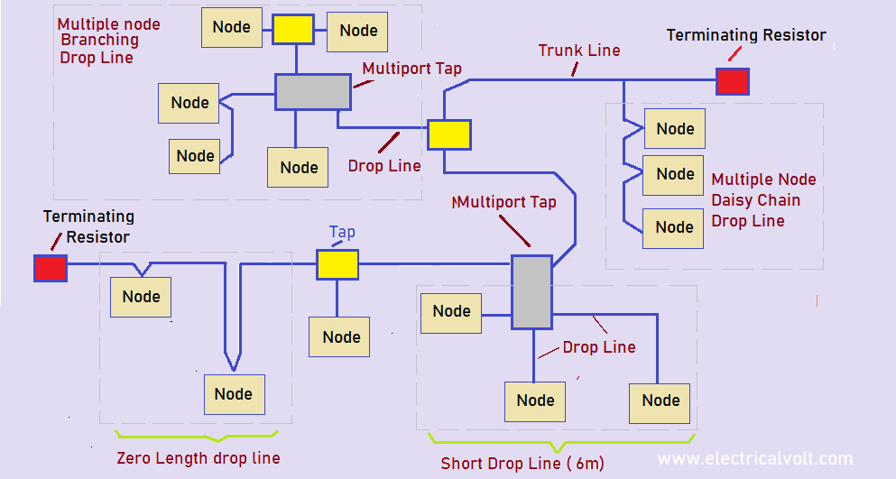
The DeviceNet medium has a linear bus topology.
Termination resistors must be present at each end of the main bus. Branch buses up to 6 m long (20ft) each are allowed and thus allow one or more nodes to be connected.
Branching structures are only allowed on the branch bus.
The total amount of backbone allowable on the network depends on the data rate and the type of cable used (10BASE5 or 10BASE2). The cable distance between two points in the wired network must not exceed the maximum cable distance allowed for the transmission speed.
For main buses consisting of a single type of cable, refer to the following table to define the maximum cable distance according to the data rate and the type of cable used. The cable distance between the two points includes the cable length of the main bus and branch bus present between the two points.
The DeviceNet protocol allows the use of 10BASE5 or 10Base2 cables of the same network.
Termination resistors
A termination resistor must be installed on both ends of the main bus. Resistors must meet the following requirements:
- 121 Ω
- 1% metal layer
- ¼ Watt.
Termination resistors should never be included in nodes.
Removing a node with a terminating resistor could lead to a network failure. Termination resistors should not be installed at the end of a branch bus, but only at both ends of the main bus.
Connectors
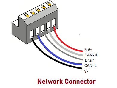
Wire Colors and Pinots. All connectors must support five conductors that supply a transmit pair, a power pair, and a drain wire.
Screw Connectors
The following figure shows the insulation colors and wire pinouts for DeviceNet screw Connectors.
The following designations are shown: 1.2.3.4.5. V-:
1 – (Black) CAN – L:
2 – (Blue) Drain:
3 – (Bare) CAN-H:
4 – (White) V+:
5 – (Red)
Connecting Units
The unit connector provides an attachment point on the main bus. The units can be connected to the network either directly on a socket or using a branch bus. The sockets also make it easy to remove a unit without interrupting network operation.
The sockets are
Sealed (with and without branch buses)
Bare (with and without branch buses) sockets
Network grounding
DeviceNet must be grounded at ONE location. Grounding in various locations can generate ground circuits while failure to ground the network results in increased susceptibility to voltage spikes and external noise sources. The grounding location should be at a power outlet.
DeviceNet communication protocol
At the level of the PLCs and control systems Allen Bradley of Rockwell Automation, several protocols are used
- The ControlNet
- The DeviceNet
- Ethernet/IP
ControlNet, the Industrial Ethernet communication protocol is generally used for communications PLCs, in particular with Allen Bradley PLCs and communicating with remote I/O.
The ControlNet protocol regulated by the ODA (Open DeviceNet Vendor Association) can reach communication speeds up to 5 Mbits/second. One can have up to 99 devices on a ControlNet network. These devices can be sensors also be PLCs, HMIs, etc.
DeviceNet is a communication protocol widely used with Allen Bradley PLCs, it is more of a sensor-actuator-oriented protocol. DeviceNet makes it possible to connect simple industrial devices (sensors and actuators) to higher-level devices such as PLCs programmable. It provides both power and communication.
DeviceNet Specifications
DeviceNet serves the automation industry as a digital networking system that controls data exchange and automation security. Essentially, each device on an input-output automation network constitutes an individual node. The nodes operate as a unified group overseen by industrial human controllers.
DeviceNet serves as the link between the node and the controller. DeviceNet specifications may change over time as the system evolves.
Frame
DeviceNet uses a master-slave also known as distributed control architecture that uses peer-to-peer communication. The controller serves as the master, while the nodes are the slaves.
DeviceNet defines all functions necessary from the physical implementation of the protocol through the communication network with the OSI (Open System Interconnection) platform for the link data.
DeviceNet relies on the Controller Area Network (CAN), whereas it uses the Common Industrial Protocol (CIP) to communicate across the upper layers of automation networks.
Networks
Through the Open Systems Interconnection (OSI model, DeviceNet defines a framework for implementing its network protocols in several layers. the “lower layer” of the network is the physical implementation of DeviceNet while the “upper layer” is the DeviceNet mode, or controller, interface.
Also, these layers include physical, data link, network, transport, session, presentation, and application types. CIP DeviceNet adapts to specific system needs at the network, transport, and lower layers.
Messaging
DeviceNet transmits messages between its operating nodes.
Three types of messaging are as follows.
1. Peer messaging
2. Explicit messaging
3. I/O messaging
Peer messages exchange data from one device or node, on the DeviceNet network to another. The DeviceNet controller, also known as the DeviceNet master, sends requests to networked nodes, or DeviceNet slaves, via explicit messaging. Similarly, I/O messages transmit predefined data between DeviceNet masters and DeviceNet slaves.
DeviceNet communication creates a single point of connection for configuration and control.
Features
According to the nonprofit Open DeviceNet Vendors Association (OVDA), the DeviceNet system reduces the connection points and physical size of an automation network. This routes and bridges data from other CIP networks such as Ethernet and ControlNet systems.
Got knowledge of basics in DeviceNet.