In this article, we will study the different starting methods used to start the three-phase induction motors.
A three-phase induction motor is a type of asynchronous AC motor. It is the most widely electrical motor in the industries to drive mechanical loads. When the induction motor is started, it draws a large starting current known as the inrush current of the motor.
The high starting current cause many problems in the supply system such as line voltage drop, etc. The system voltage drop affects the operation of other electrical appliances connected to the same line. Therefore, we need to adapt some methods for starting the induction motors to reduce the motor’s starting current to its permissible current range.
There are two types of three-phase induction motors.
- Squirrel cage induction motor
- slip-ring induction motor
In this article, we will discuss the starting methods of both types of induction motors.
Squirrel Cage Induction Motor Starting Methods
The following are the starting methods have been developed for starting the three-phase induction motor:
- Direct On Line (D.O.L.) Starter
- Star-Delta Starter
- Auto-Transformer Starter
- Soft starter
- Variable frequency Drive(VFD)
Direct On-Line Starter
As its name implies, when the three-phase electric supply is directly fed to the induction motor, this method of starting the motor is called a direct online starter or D.O.L. Starter. The following figure shows the circuit diagram of the direct online starter.
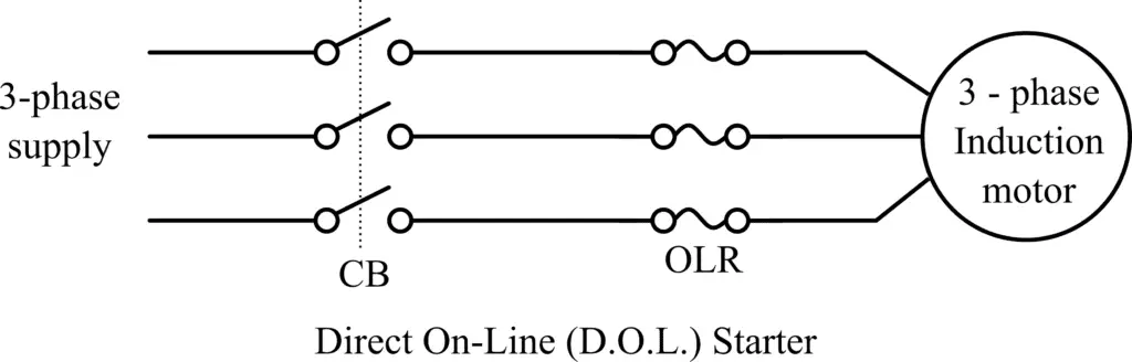
However, in this method of motor starting, the starting current is not reduced, i.e. it is very large usually 5 to 7 times the rated current. The circuit of a direct online starter consists of fuses or circuit breakers, contactors, and overload protection relays.
As in the case of line starters, there is no provision for controlling the starting current. Hence, this method is typically used for the induction motor with a rating below 5 kW.
Stator Resistance Starter
The stator Resistance Starting method is a type of reduced voltage starting. When we start an induction motor, the rotor draws a large current because the slip is equal to unity at the start. The motor current decrease as the motor accelerates and attains full speed. If we add resistance in the series with the stator resistance, the total resistance impedes the current and thus the starting current of the motor reduces.
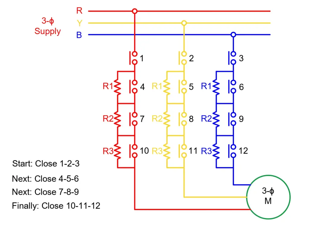
In this method, during the start, we connect external resistance in the series with each phase of the stator winding. The voltage drop takes place in the external resistance and thus the voltage across the motor terminals reduces. The reduced stator voltage leads to less stator current. Now, the stator resistance is cut out in steps from the stator circuit with motor acceleration. When the motor attains full speed the external resistances are completely cut out and the stator receives full rated voltage across the motor terminals.
The followings are the downsides of this method.
- The power loss in the external resistances takes place in the form of heat.
- The reduced voltage causes slow acceleration of the motor.
Star-Delta Starter
The star-delta starting method is a type of reduced voltage starting. The star-delta starter is the most commonly used method for starting induction motors. This method is used for the motors that are designed to operate on delta-connected stators. The circuit diagram of the star-delta starter is shown in the following figure.
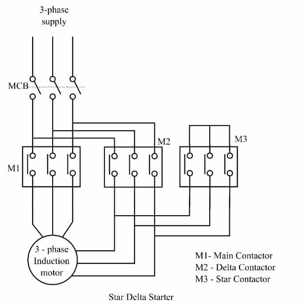
In this method, the stator winding of the motor is connected in the star during the starting period, and it is connected in the delta during the normal running condition.
When the motor is started in star connection, the supply voltage becomes 57.7 % of the normal voltage and hence the starting current of the motor is reduced. Once the motor attains about 80% of its normal speed, it is switched to a delta connection.
A double-through switch (nowadays contractors) is used for changing the connection from star to delta.
In star running, the torque delivering capacity is one-third of the full torque capacity of the motor.
Autotransformer Starter
It is also a type of reduced voltage starting. The starting method of three phase induction motor that uses an auto-transformer to reduce the starting current of the motor is called autotransformer starting. The autotransformer starter can be equally used for starting both delta-connected and star-connected three-phase induction motors. The circuit diagram of the autotransformer starter is shown in the following figure.
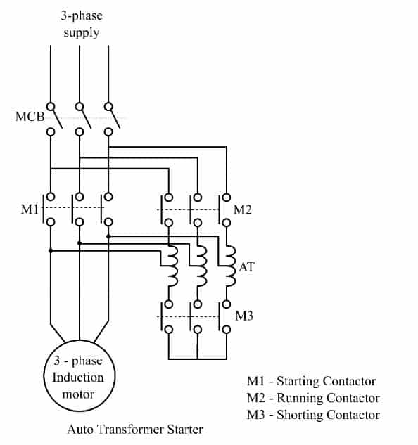
Here, the autotransformer used is a three-phase step-down transformer having different taps to obtain different voltages. The autotransformer starter generally has three steps of voltage, 50%, 65%, and 80%. The more voltage steps are possible to get a smooth acceleration of the motor. The motor is started at a lower voltage tap and the tap is changed to higher taps with the acceleration of the motor.
In this method, at starting, a reduced supply voltage is applied to the motor through the autotransformer. Once the motor attains a speed about 80% of the rated speed, the autotransformer is automatically removed from the circuit by the shorting contactor and the motor runs on the full supply voltage. It has all the motor protection features, such as no volt and overload protection.
Here, note that the starting torque of the motor is proportional to the square of the voltage. Therefore, the starting torque of the motor reduces at lower voltage and the autotransformer starters are suitable for the starting of the load that demands low starting torque.
The autotransformer starter has the following advantages.
- Low Power loss
- Low starting current
- Suitable up to 25 hp motor, depending upon the strength of power system
Soft Starter
The Soft starter is a type of reduced stator voltage electronic starter. The power circuit diagram of the soft starter is given below.
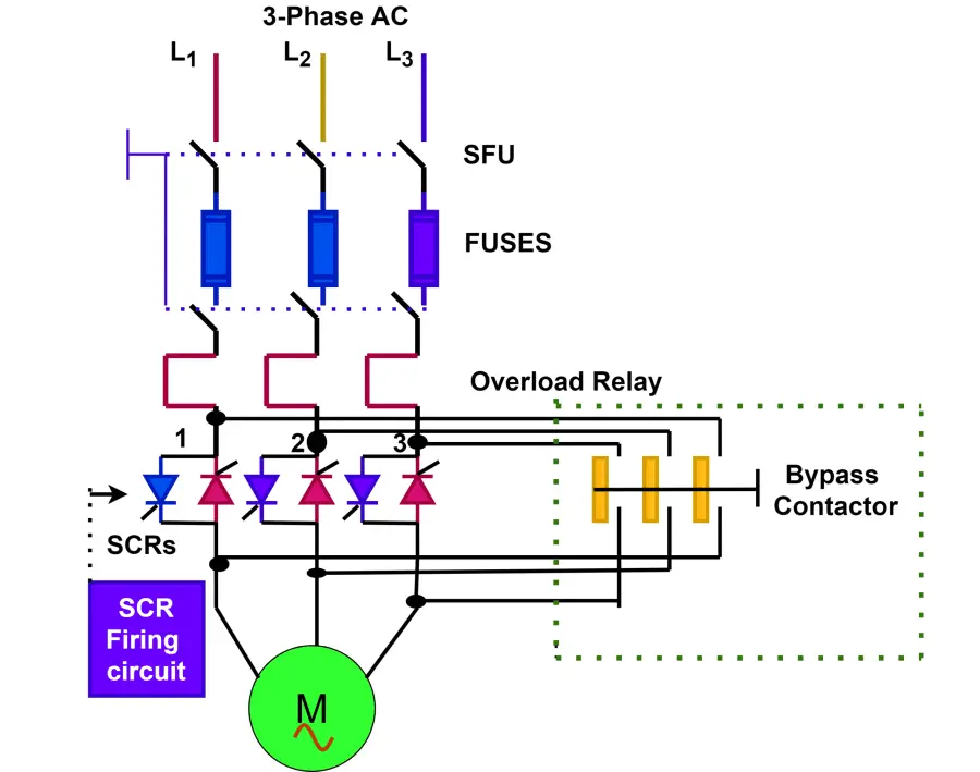
It reduces the voltage when the motor starts and increases the voltage as the motor accelerates to its full speed. Thus, by a soft starter. it is possible to regulate the voltage from zero to full line voltage. The changing firing angle of the thyristor governs the output voltage fed to the stator. The soft starter reduces the jerks on the motor and the driven equipment during starting, and hence improves the reliability.
Variable Frequency Drive(VFD)
The block diagram of VFD is given below.
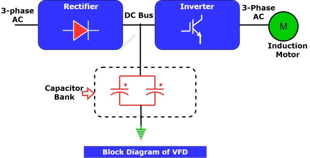
The VFD can be used as a motor starter and also for controlling the speed of an induction motor. A VFD is an advanced soft starter that controls the speed of the motor by varying the frequency. The voltage is also varied in the proportion to variation of frequency by the PWM inverter to maintain the constant flux in the motor.
Slip Ring Induction Motor Starting Methods
There are four methods used to start a slip ring induction motor. They are-
- Direct On-Line (D.O.L.) Starting
- Stator-Resistance Starting
- Autotransformer Starting
- Rotor-Resistance Starting
The first three methods- DOL starting, Stator-Resistance starting and Autotransformer starting are the same as we discussed above for the squirrel cage induction motor. The rotor resistance starting method can be used for slip-ring induction motors only.
Rotor Resistance Starter
The rotor resistance starting method is applicable for slip-ring induction motors only. Because, in this method, we insert some external resistance in the rotor circuit that is possible only in case of a wound rotor. The following figure shows the circuit diagram of the rotor resistance starter.
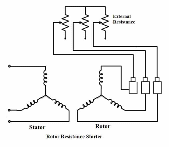
In the rotor resistance starter, a star-connected external resistor is connected in series with the rotor of the motor through slip rings and brushes. At the start-up of the motor, the complete external resistance connected to the rotor circuit reduces the starting current significantly. This resistance is gradually cut out of the circuit as the speed increases. Once the motor attains its normal speed, the external resistor is completely removed and the motor now runs as a cage rotor induction motor.
The slip ring induction motor delivers higher starting torque because of external added resistance in the rotor circuit. The external resistance also improves the power factor of the motor.
Related Articles:
Very nicely explain