The Circle Diagram of an Induction motor is very important for studying motor performance under all operating conditions. In other words, we can say that the circle diagram represents the performance of the induction motor. It is possible evaluation of motor performance parameters using a circle diagram, such as output power, losses, and efficiency.
In any industry, induction motors are extensively used in many applications such as pumping, driving mechanical loads, in conveyors, crushers, etc. Therefore, the analysis of their performances is necessary so that we can determine their various parameters like efficiency, losses, maximum power, etc.
There is a very simple method to represent the overall efficiency of an induction motor known as a circle diagram. Therefore, in this article, we will learn about the circle diagram of an induction motor, its construction, and its parts.
What is a Circle Diagram of an Induction Motor?
A circle diagram is a method of representing the overall performance of an induction motor graphically. The circle diagram of the induction motor provides information about various parameters of the motor such as starting torque, efficiency, losses, maximum power output, slip, full load current, power factor of motor, maximum torque developed in the motor, etc.
The circle diagram method is used to represent and analyze the induction motor’s performance because it is quite simple and easy to construct. It can be directly constructed from the equivalent circuit of an induction motor.
The no-load test and blocked rotor test are performed on the induction motor to draw its circle diagram. Therefore, we can also define the circle diagram of an induction motor as “a diagram that is drawn by taking the locus of current taken by an induction motor for different conditions is called the circle diagram of the induction motor”
Construction of Circle Diagram of Induction Motor
As we have described above that the circle diagram of induction can be drawn by performing the no-load test and blocked rotor (full load test). We perform these two tests on the induction motor to determine the following:
- Per phase value of no-load current (I0),
- Per phase value of short-circuit current (ISC),
- Phase angle (φ0) corresponding to no-load current, and
- Phase angle (φsc) corresponding to short-circuit current.
In this process, we also determine the value of the short circuit current corresponding to the normal supply voltage, let it is ISN.
The equivalent circuit of the induction motor is useful in determining the required parameters for drawing the circle diagram. The equivalent circuit of the induction motor is given below.
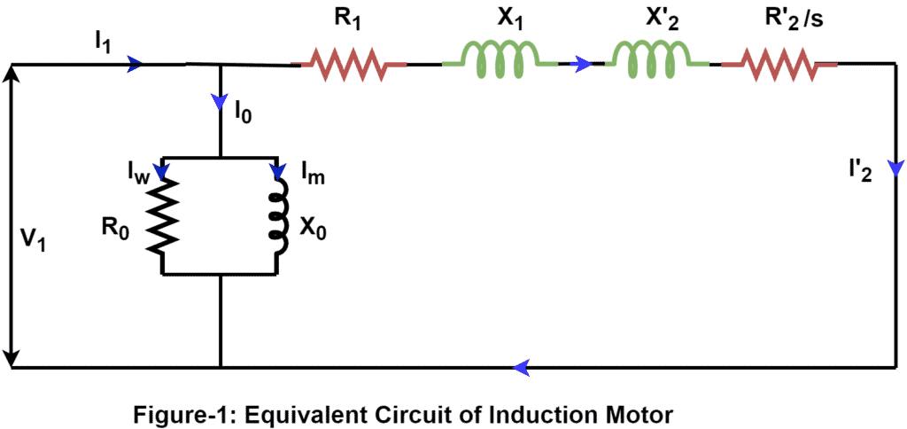
By applying KCL in the above circuit, we get
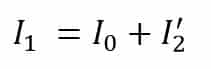
The rotor current depends on the slip(s). The slip of the motor when it runs at no-load is almost equal to zero.
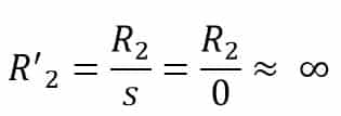
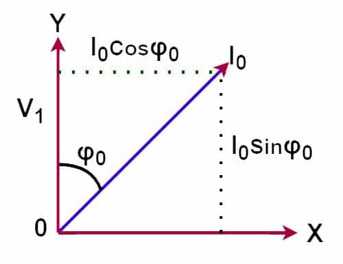
Therefore, the rotor current referred at primary(I2‘) is almost zero. Most no-load current has two components of current, one is a magnetizing component and the other is an active component or core loss component. In no load condition, the induction motor draws magnetizing current and the power factor of the motor is between 0.1 to 0.2 lagging. The magnetizing current(I0) lags the voltage(V1) as shown below figure.
Mathematical Proof of Circle Diagram
From the above phasor diagram, the no-load power(P0) of the induction motor is;
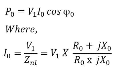
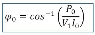
The phase angle of no-load current is;
Now, we find the rotor current referred to as the stator. From the equivalent circuit of motor it is;
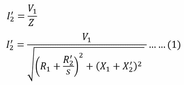
Here, the rotor referred current to the stator(I’2) lags the applied voltage(V1). The impedance triangle of the induction motor is as follows.
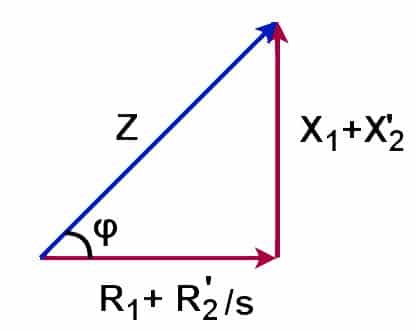
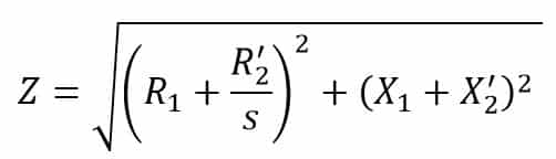
Where Z is equal to
From the power triangle of the induction motor, the value of sinφ is;
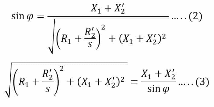
Combing equations(1) and (3). we get
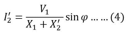
The above equation (4) represents the circle equation (r = a sin φ) in polar form, where ‘a’ is the diameter of the circle.
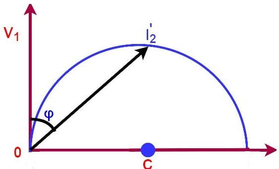
We can conclude the following points from the above figure.
Locus of Circle
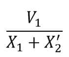
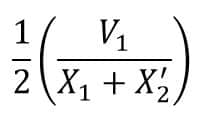
Radius of Circle
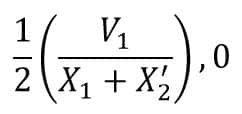
Coordinate of Center(C)
Procedure for drawing the circle diagram
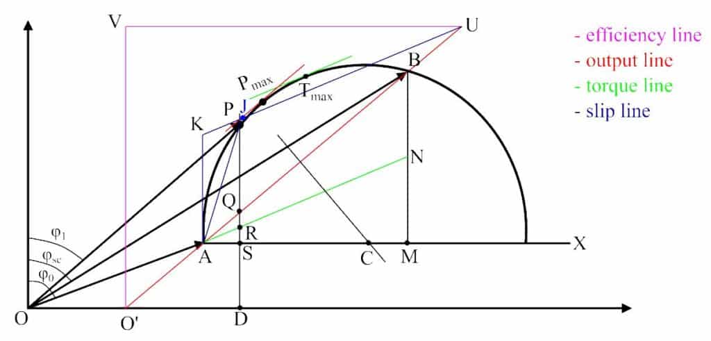
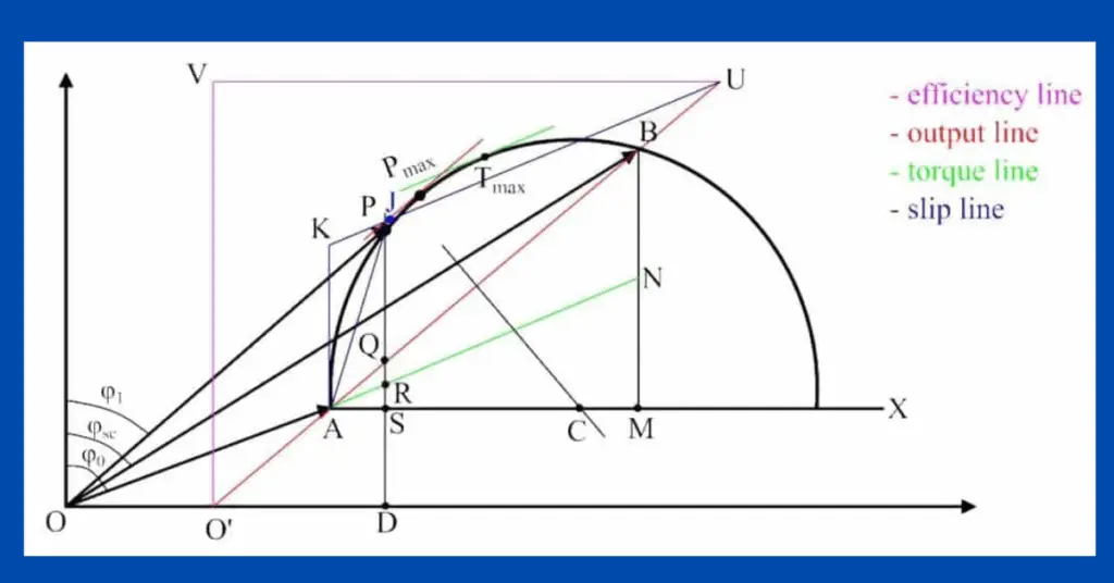
Now with these data, we can draw the circle diagram as shown in the above figure of the given induction motor as described in the following steps:
- Select a suitable scale and draw a vector OA whose length is equal to the value of no-load current I0 and the phase angle with the vertical axis is φ0.
- Draw a horizontal straight-line AX.
- Draw a vector OB whose length is equal to short-circuit current (ISN) corresponding to the normal supply voltage and the phase angle with the vertical axis is φsc, and join AB.
- Draw a perpendicular bisector to line AB, it meets the horizontal line AX at point C.
- Assume point C as the center and draw a portion of a circle passing through points A and B. This portion of the circle is the locus of input current and forms the circle diagram of the induction motor.
- From point B, draw a vertical line BM to meet the line AX, and divide the BM at a point N such that
- Now, for a given operating point P, draw a vertical line PQRSD, where,
- If we draw tangents to the circle diagram parallel to the output line and the torque line respectively. Then, the points where these two tangents touch the circle diagram represent the points of maximum power and maximum torque respectively.
Parts of Circle Diagram of Induction Motor
Efficiency Line
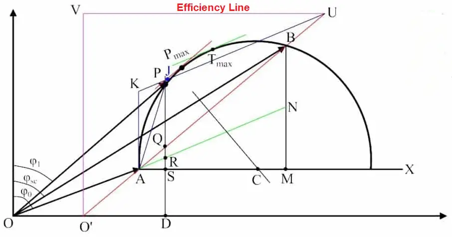
Step 1 – Extend the output line AB backward to meet X-axis at point O’.
Step 2 – From any convenient point, say V, on the output line, draw a horizontal line UV which meets the vertical from point O’. The line UV is the efficiency line of the motor.
Slip Line
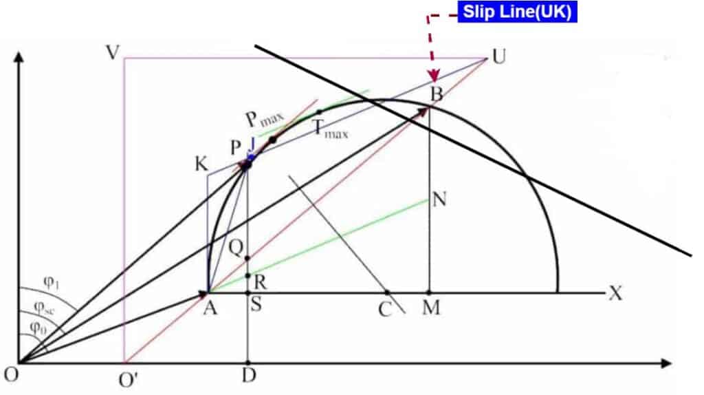
Step 1 – Draw a line parallel to the torque line, say UK, meeting the vertical line through point A at point K.
Step 2 – The line ‘UK’ is the slip line of the induction motor. Now, to find the slip corresponding to any operating point P, draw a line from point A through P to meet the slip line at point J. The line KJ is the slip of the motor.
Conclusion
Therefore, in this article, we have explained the circle diagram of the induction motor along with its construction and parts. As we can observe, the circle diagram is a simple graphical method to determine the overall performance of an induction motor.