In Plugging or Reverse Current Braking, supply polarity of armature voltage of DC motor is reversed to rapid stop the motor. The armature voltage(V) and back EMF (Eb) acts in the same direction during plugging. In plugging motor exerts opposite torque to retard its speed. The application of the plugging is to immediately stop the DC motor or AC motor.
Plugging of Separately Excited DC Motor
The plugging or reverse current braking is applicable for both AC motor and DC motor. We shall discuss the plugging mechanism of separately excited DC motor and DC series motor in this section.
Plugging Mechanism of DC Motor
The separately excited DC motor has separate field winding, and we govern the field flux in the motor by controlling the field voltage.
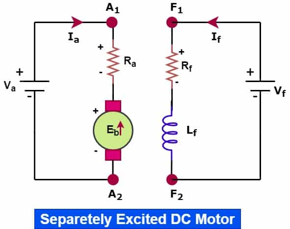
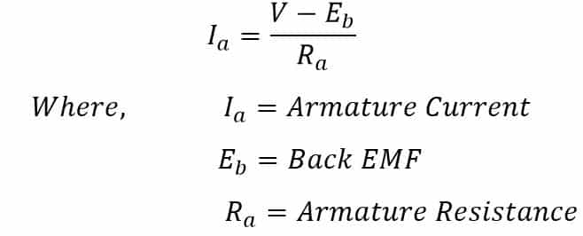
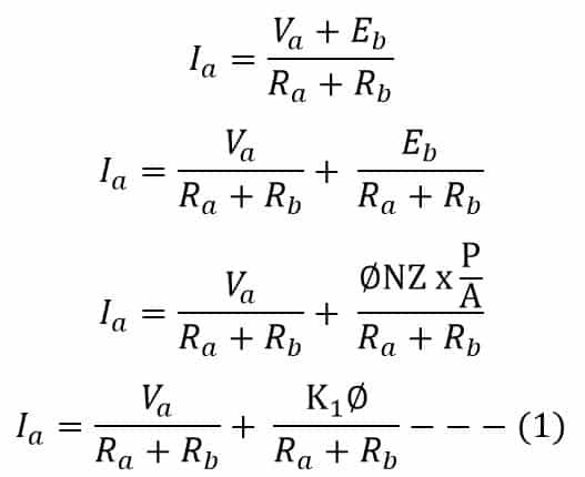
In motoring operation, the back EMF opposes the armature voltage and, thus the armature current almost remains constant. Armature current in motoring action is ;
During plugging, the armature voltage polarity is reversed. However, the back EMF polarity can not change instantly. And, the polarity of the armature voltage and back EMF is not the opposite. Therefore, the armature current increase drastically.
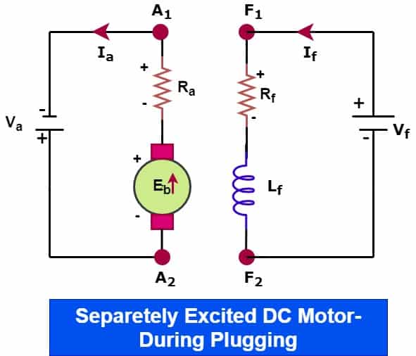
In plugging operation, the armature current direction is reversed, and therefore plugging is also called reverse current braking. The torque produced during plugging just opposes the torque produced during motoring and thus plugging retard the motor speed and brings it to a standstill.
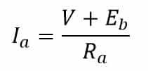
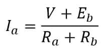
The effective voltage across the armature is (V+Eb) during plugging.The armature current during braking is;
If we compare the armature current in motoring and plugging, the armature current during plugging is about two times of the armature current during motoring. Braking torque produced by the motor depends on the following.
- Armature current
- Field Flux
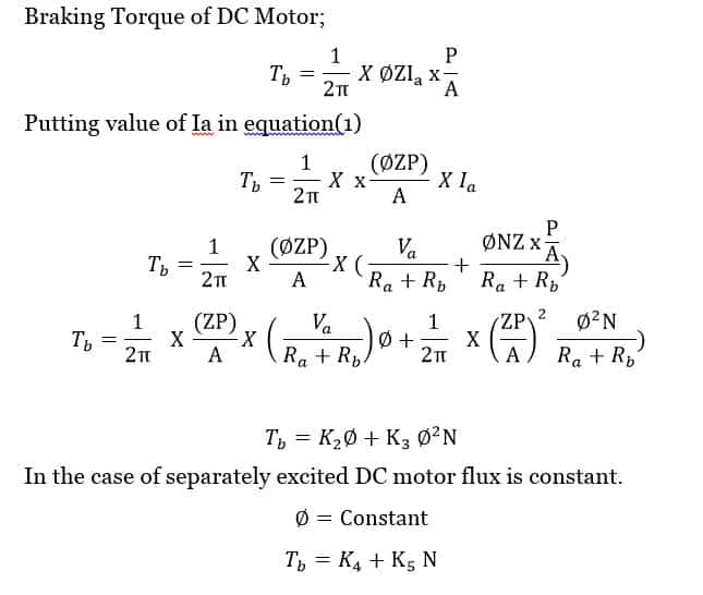
The field flux is constant in the case of a separately excited DC motor, hence braking torque is proportional to the armature current.
| Tb ∝ Ia , Where, Tb is braking Torque |
In this case, very high braking torque is produced. The energy is dissipated as heat energy in the armature. In this condition, the armature winding may burn out if the current flow for a longer time period. Therefore, it becomes necessary to limit the armature current for the protection of the DC motor. In this case, very high braking torque is produced. The energy is dissipated in the armature of the DC motor.
The back EMF reduces when the motor retards, and the back EMF becomes zero after stopping the motor. If the armature supply is not removed after the motor attains zero speed, the motor starts in the reverse direction. A speed switch mounted on the motor shaft or proximity switch arrangement senses the speed of the motor. When the motor attains zero speed during plugging, the armature voltage is cut off.
Plugging Operation of DC motor
The sequence of plugging operation of separately excited DC motor is given below.
- Motor running in the clockwise direction
- Armature voltage removed
- The motor does not come to halt because of inertia
- After removing armature voltage, the armature voltage is applied with supply polarity reversal
- The back EMF now support armature voltage
- The armature current direction reverse
- Motor turns in an anti-clockwise direction exerting the counter-torque to slow down the motor
- Motor speed reduces to zero. It is sensed with a speed switch
- Armature voltage is switched off when the speed of the motor is zero.
How to Limit the armature current of DC Motor during plugging?
A large armature current flow during plugging. In order to limit the armature current to a safe value, it is necessary to insert a resistance in the series with the armature while reversing the polarity of the armature supply voltage.
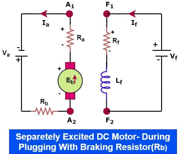
The resistance RB limits armature current. The armature current after insertion of resistance Rb during plugging is;
The braking torque Tb reduces with the insertion of the braking resistor, but it is essential to limit the armature current to a safe value.
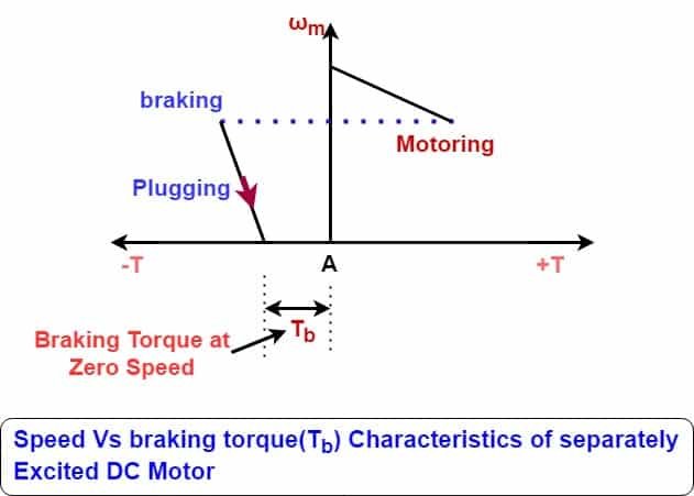
Speed Vs braking torque Characteristics of separately Excited DC Motor during motoring and plugging
Why Speed Switch is used to sense the Zero speed of the motor during plugging?
Speed of the motor reduces to zero, however, the motor has counter torque and, if the armature supply is not cut-off at this instant, then the motor will operate in the motoring zone(3rd Quadrant). Therefore, it is essential to cut off the armature supply when motor speed is zero after plugging.
Plugging in DC Series Motor
Fort plugging in DC series motor, the direction of the motor speed is reversed by either changing the polarity of the field winding or armature winding. A resistance is put in series with the field and armature winding to limit the armature current to a safe value. The polarity of both the winding is not changed because in this speed direction of speed does not change.
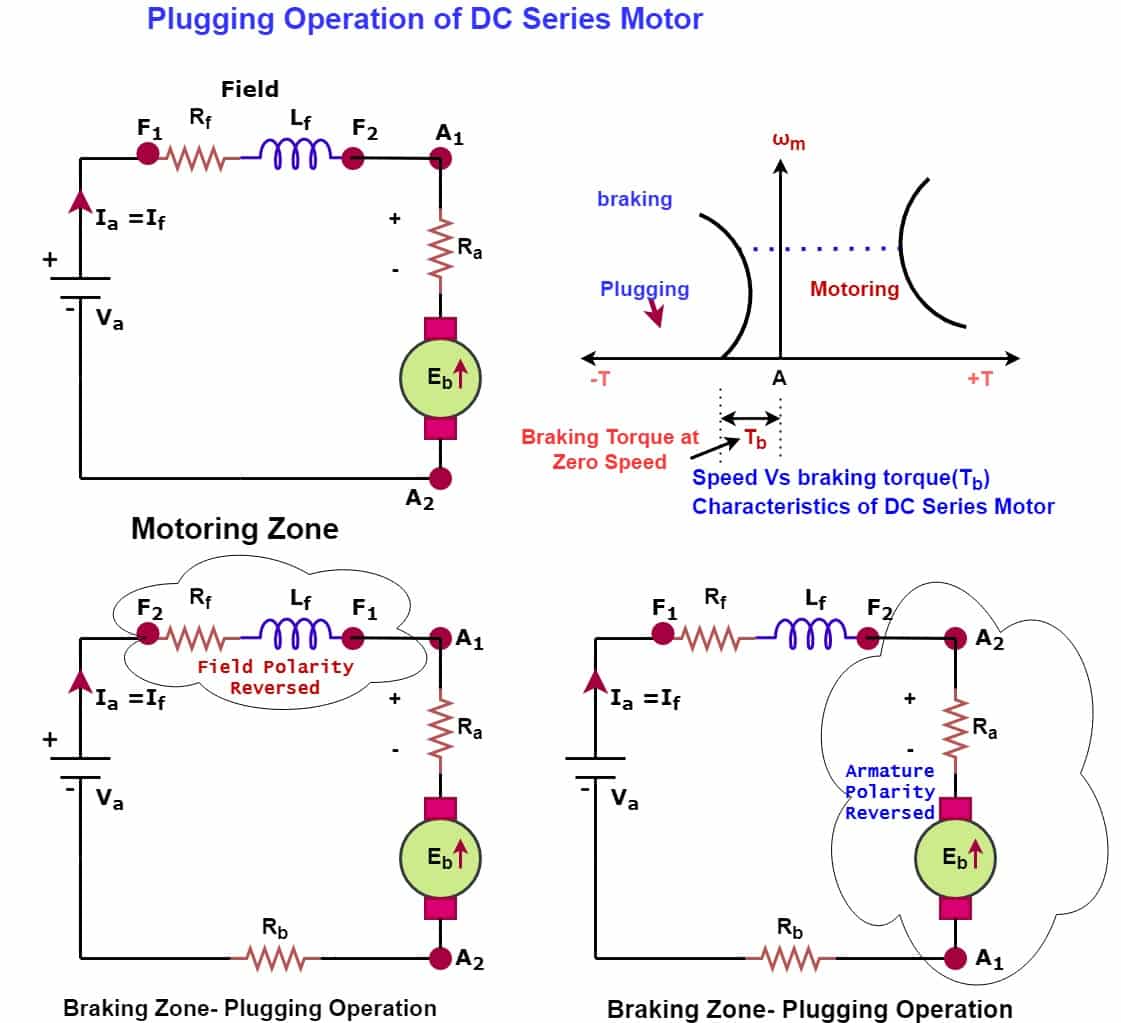
From the speed Vs braking characteristics graph, it is clear that the motor can speed up in the reverse direction if the armature supply is not switched off when the speed of the motor is zero. The reason of this is torque is not zero when the speed of the motor is zero. Therefore, a speed switch for sensing speed zero is used. When the speed switch senses the speed zero, the speed switch contact switch off the armature supply.
DC Motor Braking Torque Formula Derivation
The armature current during plugging of DC motor is;
Braking torque of DC motor is;
Disadvantages of Plugging
- Highly inefficient- Heat loss in the armature and the external resistance
- It produces a high mechanical impact load on the motor and connected equipment
Application of plugging
The plugging creates more stress on electrical and mechanical components, but it provides a faster stop than dynamic braking methods. The plugging is used for the following applications where a rapid stop of the motor is required.
- In controlling elevators
- In cranes
- Rolling Mills
- Weigh Feeders
- Vibro- feeders
- Belt Conveyors
- Printing Presses
- Machine tools, etc.
Read Next: