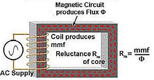
Magnetic reluctance is the opposition to magnetic flux in a material, similar to electrical resistance in a circuit. It is a key parameter in magnetic circuit design and helps engineers analyze components like transformers and motors.
Reluctance Meaning in Simple Terms
In magnetic circuits, reluctance meaning refers to the opposition a material offers to magnetic field lines. It is similar to electrical resistance, but instead of restricting current flow, it resists the flow of magnetic flux.
What is Magnetic Reluctance?
The reluctance is the property of the magnetic material, which provides opposition to the flow of magnetic flux through a given volume of space or material.
Good magnetic materials have low reluctance with high permeability.
Comparison of Magnetic and Electric Circuit
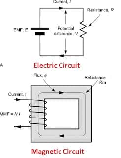
The magneto-motive force(MMF) is equivalent to emf in the electric circuit. Flux is analogous to the electric current, and the reluctance is analogous to the resistance in an electric circuit.
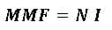
The Magneto-motive force MMF produced is equal to the product of the current and the number of turns(N).
The current flowing in the coil produces the magnetic flux (Φ), which travels through the magnetic core. The magnitude of the flux depends on the MMF and the reluctance of the magnetic circuit.
If uniform section having different values of length, cross-section area, and permeability are added, the non-uniform magnetic circuit can be made.
A non-uniform magnetic circuit’s total reluctance is the sum of individual section reluctances.
The table below summarizes the key analogies between magnetic and electrical quantities:
| Magnetic Term | Analogous Electrical Quantity | Unit |
| Reluctance (ℜ) | Resistance (R) | AT/Wb |
| Magneto-Motive Force (MMF) | Electromotive Force (EMF) | Ampere-Turns |
| Magnetic Flux (Φ) | Electric Current (I) | Weber (Wb) |
| Permeance | Conductance | Wb/AT |
Read detailed article on: Difference between Magnetic Circuit and Electric Circuit
Magnetic Reluctance Formula and Unit
The reluctance( Rm) of the magnetic circuit can be expressed as ;
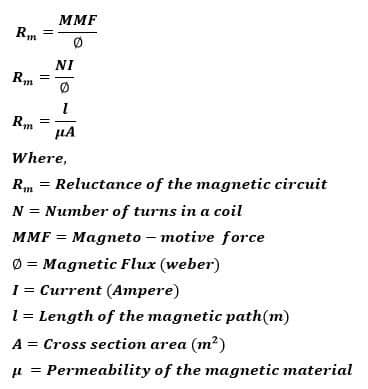
SI unit of reluctance is AT / Wb (ampere-turns / Weber). Reluctance increases with path length and decreases with area and permeability.
Example: Calculating Magnetic Reluctance
Let’s understand how magnetic reluctance is calculated with a simple example.
Problem:
A magnetic core has a length of 0.5 meters, a cross-sectional area of 0.002 m², and a relative permeability (μᵣ) of 1000. The permeability of free space (μ₀) is 4π × 10⁻⁷ H/m.
Calculate the magnetic reluctance (ℜ) of the core.
Solution:
- Length, l = 0.5 m
- Area, A = 0.002 m²
- μ = μ₀ × μᵣ = 4π × 10⁻⁷ × 1000 = 1.2566 × 10⁻³ H/m
Now apply the reluctance formula:
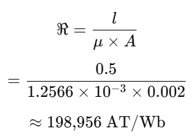
ℜ = l / (μ × A)
ℜ = 0.5 / (1.2566 × 10⁻³ × 0.002)
ℜ ≈ 198,956 AT/Wb
Permeance vs Reluctance
The permeance is one of the parameters that measure the property of the magnetic circuit to allow the magnetic flux to pass through it.
It is expressed by the following expression.
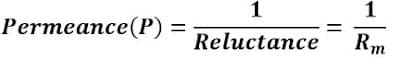
Permeance is the inverse of reluctance, just as conductance is to resistance.
| Parameter | Reluctance (ℜ) | Permeance (℘) |
| Definition | Opposition to magnetic flux | Ease of magnetic flux flow |
| Unit | Ampere-turns per Weber (AT/Wb) | Weber per Ampere-turn (Wb/AT) |
| Formula | ℜ = l / (μ × A) | ℘ = μ × A / l |
| Relationship | Inversely proportional to permeance | Inversely proportional to reluctance |
| Analogy | Similar to resistance | Similar to conductance |
Conclusion
Magnetic reluctance is a core concept in electromagnetic theory, essential for understanding magnetic circuits. It helps engineers design efficient transformers, inductors, and other magnetic devices.
Knowing the formula and unit (AT/Wb) allows accurate calculation of magnetic performance.
FAQs
In electrical engineering, reluctance refers to a property of a magnetic circuit where the material resists the formation of magnetic flux. It is influenced by the length, cross-sectional area, and permeability of the material through which the flux flows.
The SI unit of reluctance is ampere-turns per weber (AT/Wb). This unit reflects the magneto-motive force (MMF) required to drive one weber of magnetic flux through a magnetic path.
Magnetic reluctance is used in the analysis and design of magnetic circuits found in electrical machines like transformers, inductors, relays, and motors. Understanding reluctance helps engineers optimize magnetic core materials for better energy efficiency and performance.
Related Articles: