The transformer is a vital link between the load and the supply. The efficiency of the transformer is very important in view of energy saving. The transformer supplies the required power to the load at the specified voltage.
How Load Affects Transformer Efficiency
The transformer supplies power to multiple loads, each operating for different durations. As the load on the secondary side fluctuates with these varying running hours, the overall efficiency of the transformer also changes accordingly.

Transformer Behavior Under No-Load and Load Conditions
Under no-load conditions, the transformer draws only a small magnetizing current from the primary, which accounts for core (iron) losses. This current is mostly reactive, resulting in a low power factor.
As the load on the secondary increases, the transformer supplies more current, causing both primary and secondary currents to rise. This leads to increased copper losses and a slight drop in the secondary voltage, known as voltage regulation.
What is Transformer Efficiency?
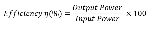
Transformer efficiency is the ratio of output power to input power, typically expressed as a percentage. It shows how effectively a transformer delivers power to the load.
Efficiency (η) = (Output Power / Input Power) × 100%
Formula for Transformer Efficiency
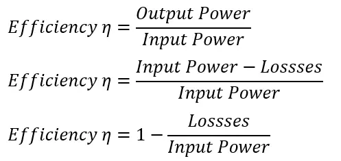
Efficiency η can be expressed in percentages as
Efficiency Formula in Terms of Input Power
The efficiency of the transformer can be expressed in terms of input power and losses.
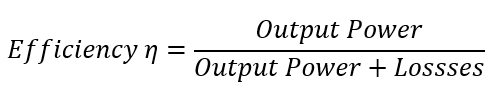
Efficiency Formula in Terms of Output Power
The efficiency of the transformer can be expressed in terms of output power and losses.
Losses in Transformer
The losses in a transformer at given loads must be calculated to determine the efficiency of the transformer. The following losses occur in a transformer.
1. No load losses
2. Primary Copper loss
3. Secondary Copper loss
4. Stray loss
5. Dielectric loss
Core Losses (Iron Losses) in Transformer
No load loss can be categorized into – The Eddy current loss and Hysteresis loss.
Eddy Current Loss
Eddy current loss occurs due to the induced voltages in the steel components of the transformer core, causing circulating currents within the core laminations. These circulating currents lead to power loss in the form of heat.
The eddy current loss can be calculated using the following formula.
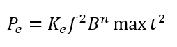
t is the thickness of the lamination. The use of thin lamination can reduce the eddy current loss.
Read detailed article on: What is Eddy Current Loss?-Definition and Expression
Hysteresis Loss
Hysteresis loss occurs due to the repeated magnetization and demagnetization of the core material. The energy used to realign magnetic dipoles during each cycle is lost as heat.
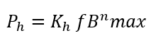
The hysteresis loss is given by the formula:
The total core loss in a transformer is the sum of hysteresis loss and eddy current loss. It is determined using the open-circuit test.
Read detailed article on: No Load Losses of Transformer – Formula & Core Loss
Copper Losses in Transformer
The copper loss in the transformer is load-dependent, which increases with increased loading on the transformer.
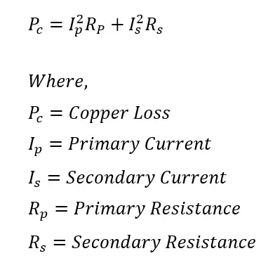
The primary and secondary copper loss occurs due to the flow of electric current in the winding. The heat loss(I2 R) occurs in the winding because of winding resistance.
The total copper loss is,
The short circuit test is carried out to determine the copper loss in a transformer.
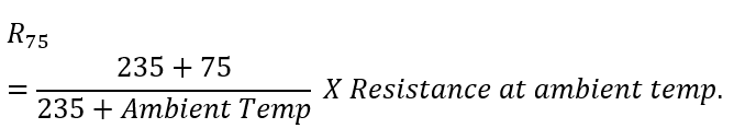
For accuracy, the winding resistance should be corrected to the standard operating temperature of 75 °C. The resistance corrected to 75 °C is given by:
Read detailed article on: Copper Loss in Transformer – Explanation, Formula & Reduction Methods
Stray Losses in Transformer
Stray loss occurs due to leakage flux in the transformer. When the transformer is at full load, some flux leaks and gets linked to the other parts of the transformer.
Dielectric Losses in Transformer
Dielectric loss occurs in the insulation of the transformer. The tanδ test can obtain the loss.
How to Calculate Transformer Efficiency
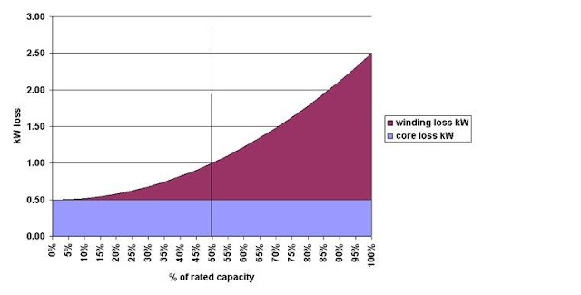
The two primary losses in a transformer are copper loss and core loss.
Core loss depends on voltage and frequency, and it remains nearly constant as long voltage and frequency unchanged. Since it does not vary with load, core loss is also referred to as constant loss. It stays fairly consistent across the full load range, from 0% to 100%.
The copper loss in a transformer varies with the load and increases as the load increases. Therefore, it is referred to as a variable loss.
Let the KVA rating of the transformer be S.
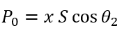
If the transformer operates at x% of its full load KVA rating, and the load power factor is Cos θ₂, then:
Output Power of the Transformer
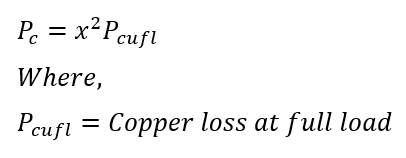
Copper Loss at Percentage Loading
Copper loss in a transformer depends on the square of the load.
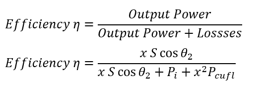
Efficiency of the Transformer at Percentage Loading
Condition for Maximum Transformer Efficiency
The copper loss is variable. The maximum efficiency of the transformer occurs when the variable loss is equal to the constant loss.
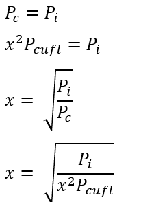
Putting value of copper loss(Pc)
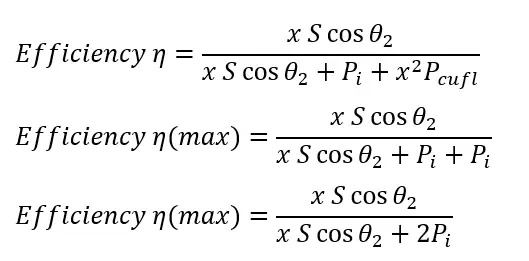
The maximum efficiency of the transformer is obtained when the core loss equals the copper loss.
Related Articles: