A DC shunt motor is known for its nearly constant speed operation, making it ideal for applications like lathes, fans, and conveyors.
In this post, we’ll explore the construction, key formulas, speed control methods, and performance characteristics of a DC shunt motor to understand how it operates and maintains stable speed under varying loads.
Construction of DC Shunt Motor
The field winding of the DC shunt motor is wound with many turns to increase the flux linkage, and the armature winding is designed to carry a higher current. This is done because the torque is proportional to the armature current and the flux.
DC shunt motor is a self-excited type of motor because the field and armature winding are energized with the same DC supply.
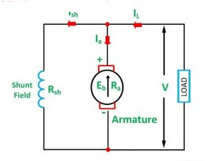
The armature winding and the field winding are connected in parallel, and a DC supply is applied to both windings.
DC Shunt Motor Formulas and Equations
When the DC voltage (V) is applied to the field and armature winding, the back EMF (Eb) is induced in the armature winding, which opposes the applied voltage.
The armature current
Ia= Eb/Ra
Where,
Ra- The armature resistance,
Eb- Back EMF
The applied voltage (V) is equal to the Ia*Ra voltage drop plus back EMF(Eb).
V = IaRa + Eb ———–(1)
Ia = Itotal- Ish ———(2)
V = Eb+( Itotal-Ish)Ra —–(3)
This is the dc shunt motor voltage equation, showing that the applied voltage is equal to the sum of the back EMF and the voltage drop across the armature resistance.
The field current is ;
Ish= V/ Rsh ————(4)
Where, Rsh- The Resistance of field winding
The field current remains constant for a fixed applied DC voltage(V).
DC shunt motor speed formula is derived from the relationship between speed, back EMF, and field flux. The speed of a DC shunt motor is directly proportional to the back EMF (Eb) and inversely proportional to the flux (Φ) produced by the field winding:
N ∝ Eb / Φ — (5)
Where,
N – Speed of the motor
Eb – Back EMF
Φ – Magnetic flux produced by the field winding
The above expressions are the most commonly used DC shunt motor formulas for calculating armature current, voltage drop, and field current.
- Back EMF (Eb): Eb = V − Ia × Ra
- Armature Current (Ia): Ia = (V − Eb) / Ra
- Field Current (Ish): Ish = V / Rsh
- Total Line Current (Itotal): Itotal = Ia + Ish
- Torque (T): T ∝ Φ × Ia
- Speed (N): N ∝ Eb / Φ
Speed Control of DC Shunt Motor
The speed of a DC shunt motor is given by the relation:
N ∝ (V − IaRa) / Φ
Where:
- N = Speed
- V = Applied voltage
- IaRa = Voltage drop across the armature
- Φ = Field flux
There are two primary methods to control the speed of a DC shunt motor:
1. Flux Control Method
In this method, a variable resistor (rheostat) is connected in series with the field winding. By increasing the resistance, the field current (Ish) decreases, reducing the flux (Φ). Since speed is inversely proportional to flux, the motor speed increases.
- Used when: Higher-than-rated speed is required
- Advantages: Simple and efficient for speed above base speed
- Limitations: Speed control is limited and not suitable for low-speed operation
2. Armature Voltage Control Method
This method varies the voltage applied to the armature while keeping the field voltage constant. Since speed is directly proportional to the armature voltage, increasing the voltage increases the speed and vice versa.
- Used when: Smooth control below rated speed is needed
- Advantages: Good speed regulation, precise control
- Limitations: Requires a variable voltage supply
These methods help achieve the required motor performance for applications needing variable speed, such as lathes, fans, and blowers. The flux control method is widely used due to its simplicity and cost-effectiveness for applications needing speeds above the rated value.
Characteristics of DC Shunt Motor
Torque- Armature Current (T-Ia)characteristics
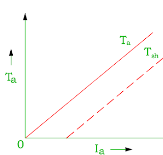
If the applied voltage is kept constant, the field flux remains constant. The torque of the DC motor is proportional to the product of the flux and the armature current.
Ta 𝝰 Φ Ia
Ta 𝝰 Ia ( Φ constant)
The characteristic of torque and armature current is a straight line from the origin. The shaft torque is always less than the gross torque. This is because of stray losses.
The heavy starting loads require more armature current, so the shunt motor should not be started on heavy loads.
Speed vs Armature Current (N-Ia) Characteristic
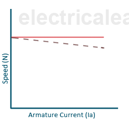
The speed of the motor is directly proportional to the back EMF(Eb) and reciprocal to the flux.
N α Eb / Ф
The back EMF(Eb)= V-Ia.Ra
With an increase in the armature current with a load, the back EMF decreases very small due to a small IaRa voltage drop as the armature resistance value is very low. The flux also decreases with an increase in load current due to the armature reaction. Thus, the ratio of Eb/Φ remains almost constant, and the motor speed is almost constant with an increase of armature current with loading. Therefore, the DC shunt motor is a constant-speed motor.
Speed-Torque(N-T) characteristics
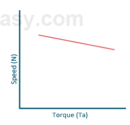
The change in the speed of the motor is negligible with the torque.
Why DC Shunt Motor Runs at Constant Speed?
When the loading on the motor is increased, the speed of the motor decreases momentarily. With the speed reduction, the back EMF also gets reduced—consequently, the armature current increases because of the reduction of the back EMF.
Ia= (V-Eb)/Ra
The increased armature current produces more torque. The increased amount of torque increases the speed and provides compensation for speed loss on loading.
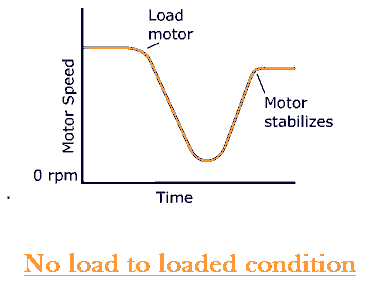
Thus, the motor maintains the constant ratio of Eb/flux and constant speed.
Why a DC Shunt Motor Should Not Be Started Under Heavy Load
The DC shunt motor should not be started at load. The back EMF (Eb) is zero when the motor is started. The DC shunt motor draws a large armature current because the back EMF is zero at the start.
If the motor is started at a heavy load, the armature current exceeds to a greater extent. The large armature current causes heating in the armature winding, and the insulation of the armature winding might fail.
Therefore, the DC shunt motor should not be started at heavy loads.
Conclusion
The DC shunt motor is a popular choice in industrial applications due to its ability to maintain nearly constant speed under varying load conditions.
Its construction allows for easy speed control through either field flux variation or armature voltage regulation. Understanding key formulas—such as those for back EMF, armature current, and speed—is essential for analyzing motor performance.
Additionally, knowing the characteristics and safe starting conditions helps ensure efficient and reliable operation. With its predictable behavior and stable operation, the DC shunt motor remains a vital component in the world of electric drives.
Related Articles: