Understanding the active region, saturation region, and cutoff region of a Bipolar Junction Transistor (BJT) is fundamental for both analog and digital circuit design. These regions define how the transistor behaves—whether it acts as an amplifier, a closed switch (ON), or an open switch (OFF).
The transistor can be used as a switch or as an amplifier by forward or reverse biasing the emitter-to-base and base-to-collector junctions. Based on biasing conditions, the transistor operates in one of the three regions:
- Cutoff Region
- Active Region
- Saturation Region
These regions define the transfer characteristics and determine whether the transistor is ON, OFF, or amplifying signals.
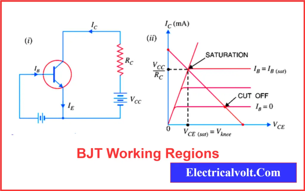
Transistor Working Regions Overview
A Bipolar Junction Transistor (BJT) operates in three major regions depending on how the junctions are biased:
- Cutoff Region – Both junctions reverse biased
- Saturation Region – Both junctions forward biased
- Active Region – Emitter-Base forward biased, Base-Collector reverse biased
These regions are crucial to understand transistor operation in switching and amplification applications.
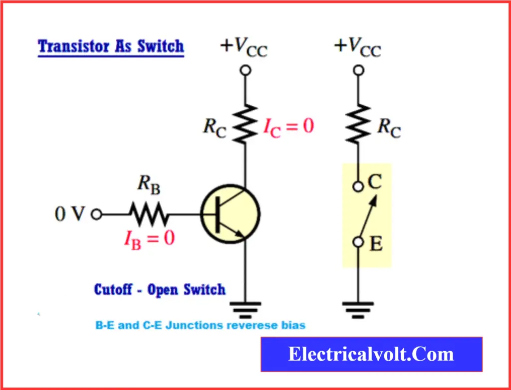
Transistor as a Switch
When used as a switch, the transistor operates in either cutoff or saturation mode.
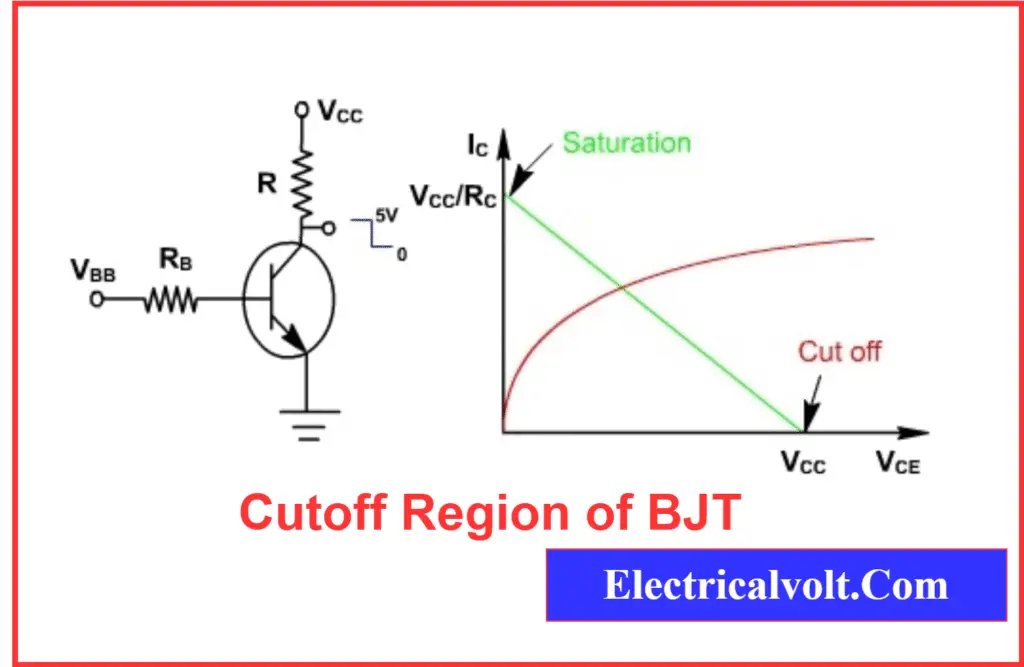
Cutoff Region of BJT
In the cut-off region, both the emitter-to-base (EB) and base-to-collector (BC) junctions are reverse-biased. This prevents current flow through the transistor.
- Base current (IB) = 0
- Collector current (IC) ≈ 0
- Emitter current (IE) ≈ 0
- Collector-emitter voltage (VCE) = High
The transistor acts like an open switch (OFF state).
In the off region, the output of the transistor VCE, IC, IB, and IE=0
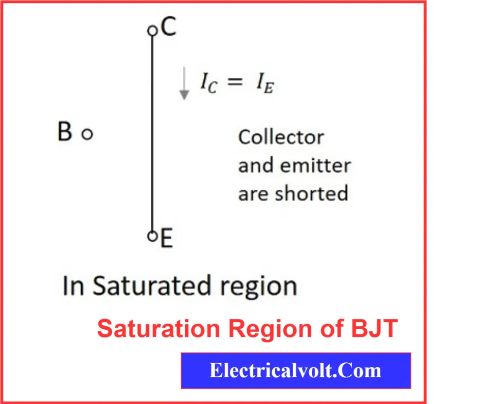
Saturation Region of BJT
In the saturation region, both the EB and BC junctions are forward-biased.
- The base current is sufficient to allow maximum collector current.
- VCE is very low, typically around 0.2V.
- The transistor behaves like a closed switch.
Transistor as an Amplifier
When the transistor is used as an amplifier, it operates in the active region.
Active Region of BJT
In the active region:
- The emitter-to-base junction is forward-biased
- The base-to-collector junction is reverse-biased
This biasing allows the transistor to act as a linear amplifier, where the collector current is controlled by the base current.
The relationship:
IC = β × IB
Where:
- IC = Collector current
- IB = Base current
- β = Current gain (hFE)
Read detailed article on: Bipolar Junction Transistor (BJT) as an Amplifier
Comparison Table: Active, Saturation, and Cutoff Regions
The table below summarizes the transistor’s behavior in the three main working regions:
| Parameter | Cutoff Region | Active Region | Saturation Region |
| EB Junction Bias | Reverse-biased | Forward-biased | Forward-biased |
| BC Junction Bias | Reverse-biased | Reverse-biased | Forward-biased |
| Base Current (IB) | 0 | Small | High |
| Collector Current (IC) | ≈ 0 | IC = β × IB | Maximum |
| VCE | High (≈ Vcc) | Moderate | Low (≈ 0.2V) |
| Mode of Operation | Open Switch (OFF) | Amplifier | Closed Switch (ON) |

Related Articles:
Really interested.
Very Helpful
this has really given a good insight, thanks……