What is a bench set?
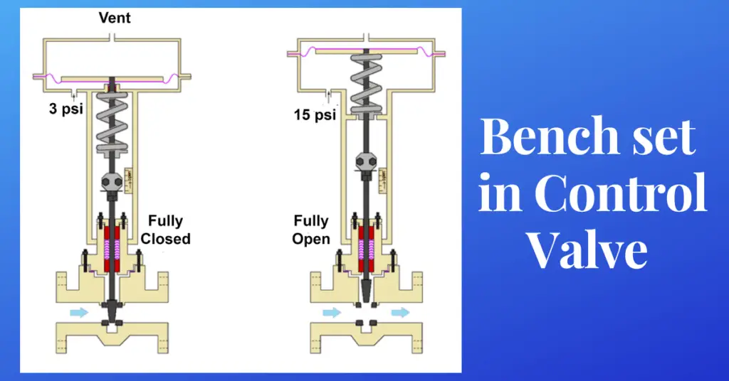
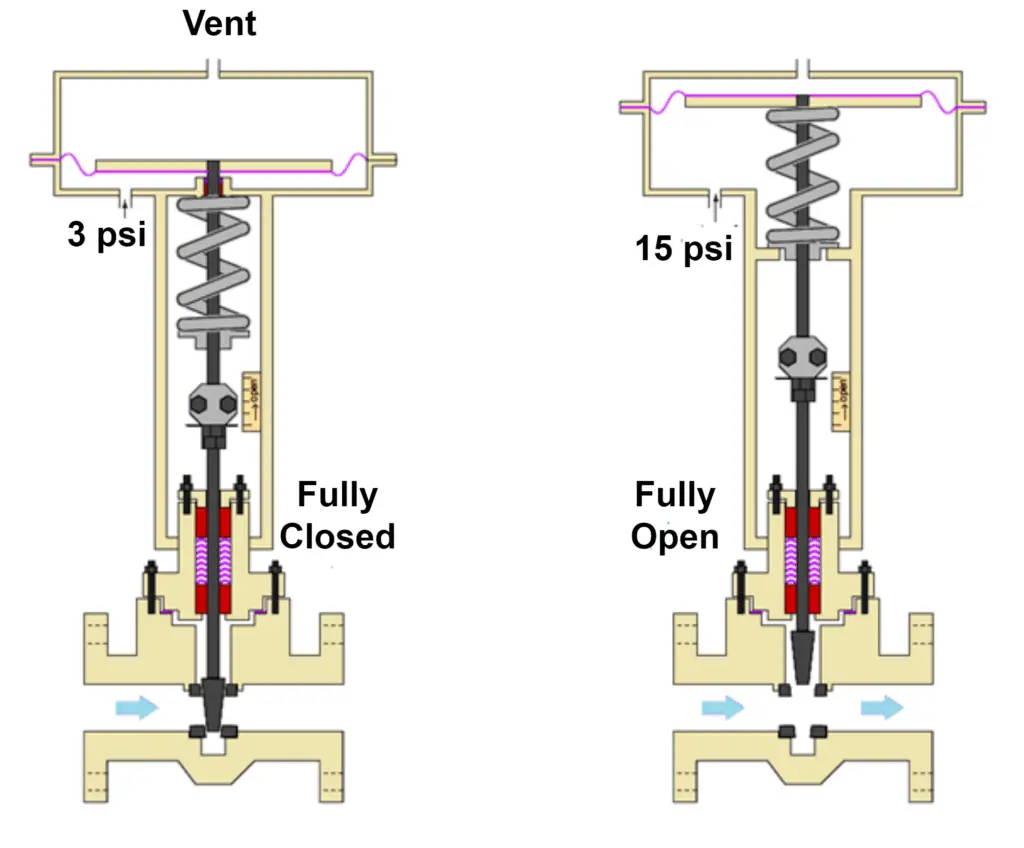
One of the most important parameters in the control valve is the bench set. The bench set of a control valve defines the amount of air pressure required to fully open/close the control valve. The bench set ensures proper sitting of the control valve’s plug on the control valve’s seat. The value of the bench set varies for every control valve. To be precise, the bench set is the value for an actuator. Every actuator has its own defined bench set.
What are the conditions needed for the bench set?
- The actuator should not have any passing during the bench set setting. So always check the actuator for passing issues.
- The actuator’s vent ports should be having a free path for the airflow. No air restriction should be there on the vent port side. If any restriction is present, then the actuator’s response will be totally different.
- The movement of the stem should be smooth. Sometimes in old actuators, due to foreign material on the actuator’s stem or due to corrosion, the actuator’s movement is not smooth. So, ensure the smooth movement of the actuator while opening and closing.
How to adjust the bench set?
Bench setting for a control valve can be either done when the control valve is installed in line or when the control valve is in dropped condition. Always try to set the bench set when the control valve is in dropped condition. Because in this condition, the control valve’s stroke will be free and without any friction.
Some basic tools and tackles are needed to perform the bench set setting of a control valve. They are mentioned below:
- Vise
- A proper actuator or properly overhauled actuator
- Datasheet of the actuator
- Properly regulated air supply
- Calibrated pressure gauge
- Flexible tubing
- Fittings
- Spanners
- Teflon tape
Steps for bench set adjustment
Below mentioned steps should be followed to set the bench set of a control valve.
- Properly mount the actuator on the vise.
- Connect the instrument air supply to the actuator using the flexible tubing. Also, connect a pressure gauge in the instrument air supply line to monitor the instrument air pressure.
- Now note down the actuator’s initial position of the stem on the scale.
- Start increasing the instrument air using the regulator. Keep monitoring the actuator for movement when the actuator gives movement, note down the instrument air supply pressure.
- Now after noting down the minimum air pressure or say a lower limit of the air pressure, we need to know the upper limit of the air pressure. So slowly increase the pressure of the instrument air pressure using the regulator. Note down the instrument air pressure at the maximum travel of the actuator as per the datasheet.
- If any discrepancy is found, then set the spring load using the spring tension adjusting nut.
- Again, repeat the steps from step number 3. If still the setting does not work, then the spring might be damaged or the incorrect type of spring is used spring.
- Try replacing the spring.
- For example, the bench set of the control valve shown in the figure is 3 psi to 15 psi as the control valve gives 0% to 100% movement in 3 psi to 15 psi air pressure.