When energizing a power transformer, the transformer draws a magnetizing current. The magnitude of the magnetizing current is several times higher than the rated current of the transformer.
This article explains the causes, effects, and methods to control transformer magnetizing inrush current. You’ll learn how residual flux, switching instants, and tap changer positions influence inrush, along with ways to minimize it for improved transformer reliability.
Effects of Magnetizing Inrush Current
Even the magnitude of the inrush current may rise up to ten times the rated current, and its duration may last about 10 cycles. The high current at the charging time creates mechanical stress and noise in the transformer.
In addition, the high magnetizing current creates transients in the electrical network that may also affect the operation of the other equipment. The magnetizing inrush current deteriorates the useful life of a transformer. Technically, the frequent charging of the transformer must be avoided.
Transformer Magnetizing Current Explained
When the voltage is applied to the transformer’s primary, the flux is set up in the core, and some residual flux always remains in the core due to the properties of the core material when the transformer is switched off.
The magnitude of residual magnetic flux can be 50 to 80 percent of the maximum operating flux.
The residual flux of the core gets added to the main flux when the transformer is energized. So, the net flux generated within the winding is determined by adding the residual flux of the core with the flux generated by applying a voltage to the primary winding.
When the sinusoidal voltage is applied to the transformer’s primary, the induced EMF in the primary winding is as per the below-given equation.
To dive deeper into the concept of magnetizing current under no-load conditions, read this detailed guide on Magnetization Current in Transformer.
Magnetizing Current Formula Derivation
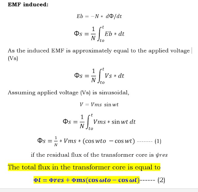
The magnetization current formula in a transformer is derived by analyzing the relationship between the applied voltage, core flux, and induced EMF. From the above equation, the core’s net flux depends on the core’s residual magnetic flux and the magnitude of the applied voltage at the instant of transformer energization.
What is Inrush Current in Transformer?
The maximum peak flux value of a transformer increases in the presence of residual flux within the core.
If the transformer is energized at t-0 of the applied voltage, i.e., at the instant when the voltage waveform crosses zero going positive, the maximum peak flux is significantly high:
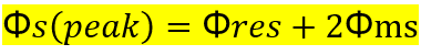
This high peak flux, especially when combined with residual flux, leads to a large magnetizing inrush current.
This sudden surge of flux causes a large magnetizing inrush current, which can lead to protective device maloperation, mechanical stress on windings, and reduced transformer life.
Understanding the causes and timing of this inrush is essential for effective transformer design and operation.
Main Reasons for Magnetizing Inrush Current in Transformer
From above, it is evident that the magnetizing inrush current of the transformer depends on the following:
- The residual magnetic flux in the core
- Number of winding turns at the time of energizing the transformer
- The instant of the applied waveform at the time of transformer charging
How to Minimize Inrush Current in Transformer?
The following methods are useful for minimization of the transformer inrush current.
Switching Transformer at Specific Voltage Instants
The charging current magnitude can vary when the transformer is charged at the different instants of the supply waveform. If the transformer is charged at the instant when the waveform is at 90 degrees, there will be no magnetization inrush current.
However, if the transformer is charged at the instant when the waveform is at zero degrees crossing, the transformer will draw a high magnetization inrush current.
Therefore, the transformer must not be charged at the instant when the input supply waveform crosses zero. The zero-crossing detection can be done, and the transformer can be charged at other instants, avoiding the zero-crossing point of the waveform.
Reducing Primary Voltage During Charging
At the time of transformer charging, a series resistance with primary winding can be inserted to reduce the voltage applied at the primary. After charging the transformer, the series resistance is bypassed for normal operation.
To limit the magnetizing inrush current of the generating station’s transformer, the generator breaker is made when the generator starts building the voltage; so at the reduced voltage, the inrush current of the transformer is minimum.
Tap Changer Position and Number of Winding Turns
The flux generated by the primary winding in the transformer is;
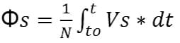
The flux generated in the primary winding is reciprocal to the number of turns of the primary winding.
With the on-load tap changer mechanism, the tap position is reduced to the minimum so that the maximum turns of the primary winding are in the circuit. After charging the transformer, the tap position can be changed as per system requirements.
When the transformer is switched off or tripped with protection faults, the tap changer can be programmed to bring the tap position back to a minimum so that the charging current can be reduced at the time of the transformer’s charging.
Conclusion
Transformer magnetizing inrush current is an important consideration in power system design and operation. It occurs primarily due to residual flux in the core and improper switching instants, often resulting in mechanical stress, false relay operation, and reduced transformer life.
Understanding the causes—such as core saturation, waveform timing, and tap changer positions—helps in developing effective strategies to minimize inrush. Techniques like controlled switching, reducing primary voltage during energization, and optimizing tap settings can significantly reduce the impact of inrush currents.
By applying these mitigation methods, power systems can enhance transformer reliability, reduce maintenance costs, and ensure smoother operation during energization.
Related Articles: