- Shunt Reactor Definition: A shunt reactor is an electrical device used in transmission systems to absorb or compensate reactive power, stabilizing voltage under light-load and no-load conditions.
- Voltage Stabilization: It maintains line voltage in high-voltage (HV) and extra-high-voltage (EHV) networks, controlling overvoltage and regulating capacitive reactive power.
- Types of Shunt Reactors: Includes dry-type, oil-immersed, and variable shunt reactors (VSRs), each suited to specific voltage levels and operational conditions.
- Construction Components: Major parts include the core (cold-rolled silicon steel), windings (copper or aluminum with insulation), cooling system (ONAN or forced cooling), and main tank (bell-type steel tank).
- Connection Method: Three-phase reactors are generally star (wye) connected, with the neutral point grounded or connected via a tertiary transformer winding.
- Loss Measurement: Losses are measured at rated voltage or scaled from lower voltage tests. The bridge method is preferred due to the reactor’s low power factor.
- Ratings and Standards: Rated in MVAr (reactive power), with voltage ratings up to 800 kV and power capacities up to 300 MVAr, following IEC 60076-7 standards.
- Applications: Used for reactive power compensation, improving system power factor, reducing transmission losses, protecting generators and transformers, and controlling electromagnetic interference.
- Difference from Power Transformers: Unlike power transformers that change voltage levels, shunt reactors primarily absorb reactive power and stabilize the system.
In an electrical power system, a shunt reactor stabilizes the transmission line voltage during light-load and no-load conditions. A typical shunt reactor is essentially a power inductor used to absorb and compensate reactive power generated in transmission systems, especially in long high-voltage lines and underground cables.
In this article, we discuss the definition, working principle, construction, types, and applications of shunt reactors in electrical power systems.
What is a Shunt Reactor?
A shunt reactor is an electrical device used to absorb or compensate reactive power in transmission systems. It is similar to a power transformer in construction but has only a single winding per phase, whereas a power transformer has two or more windings.
Shunt reactors play a crucial role in improving the power quality and energy efficiency of electrical power systems. Their primary function is to absorb excess capacitive reactive power generated in long-distance high-voltage transmission lines and cable networks. These reactors are connected in parallel (shunt) with the transmission line.
A shunt reactor operates to stabilize line voltage under load fluctuations. Therefore, it is an essential component in high-voltage (HV) and extra-high-voltage (EHV) transmission systems.
In traditional power systems, a fixed-rating shunt reactor may be permanently connected to the transmission line or switched in and out depending on system load conditions.
In practice, three-phase shunt reactors are commonly used. Their main purpose is to compensate capacitive reactive power and regulate overvoltages that occur during light-load operation or sudden load disconnections.
A shunt reactor must withstand the maximum continuous operating voltage of the system. For example, in a 440 kV power system, the reactor should be capable of operating continuously at about 105% of rated voltage.
Why Shunt Reactors Are Used in Power Systems
Transmission lines and underground cables possess inherent capacitance. In long lines, this capacitance causes the current to lead the voltage, generating capacitive reactive power, especially under light-load conditions.
Problems Caused by Excess Reactive Power
- Overvoltage in transmission lines
- Insulation stress on equipment
- Ferroresonance in transformers
- Overheating of generators in weak networks
- Reduced system stability
Role of Shunt Reactor
A shunt reactor provides inductive reactance, which:
- Absorbs capacitive reactive power
- Limits overvoltage during light load
- Improves voltage regulation
- Protects transformers and generators
Construction of Shunt Reactor
The construction of a typical shunt reactor is similar to a power transformer, but it is specially designed to handle high magnetizing current and continuous voltage stress.
The shunt reactor diaagram is shown in the image below.
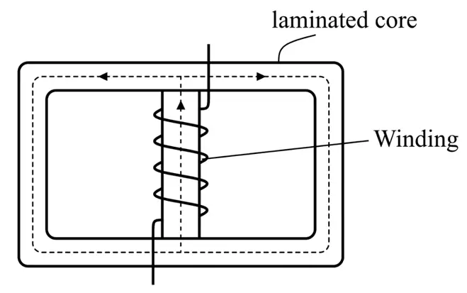
Major construction components include:
(1). Core
The core of a shunt reactor is made of cold-rolled grain-oriented silicon steel sheets, which minimize hysteresis losses. The core laminations reduce eddy current losses. In many designs, air gaps are provided in the core to limit magnetizing current.
(2). Winding
The reactor winding consists of copper or aluminum conductors insulated with paper or epoxy materials. Since the reactor operates continuously, the winding is designed for high thermal stability.
(3). Cooling System
Shunt reactors generally carry low current but operate at high voltage. Therefore, the Oil Natural Air Natural (ONAN) cooling system is commonly used. Radiator banks are attached to the main tank to improve heat dissipation. Forced cooling may be used for higher MVAr ratings.
(4). Main Tank
The main tank is typically a bell-type steel tank designed to withstand thermal expansion and internal pressure. It houses the core and windings and ensures safe and reliable operation.
Shunt reactors may be designed as oil-immersed or dry-type units depending on voltage level and application.
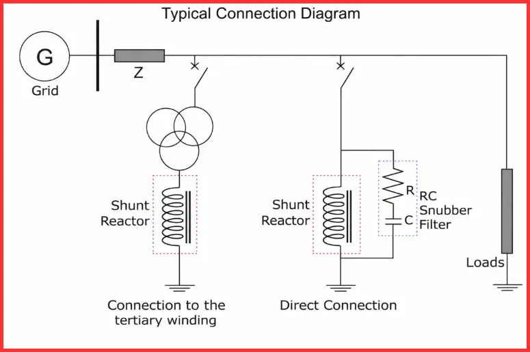
Connection Diagram of Shunt Reactor
The three reactor windings are typically connected in a star (wye) configuration, with the neutral point brought out for external access. This neutral point is either directly grounded or connected to the station earthing system through the tertiary winding of a power transformer.
A standard shunt reactor connection arrangement is illustrated in the diagram below.
Types of Shunt Reactors
Based on construction and insulation method, shunt reactors are classified into the following types:
- Dry Type Shunt Reactor
- Oil Immersed Type Shunt Reactor
- Variable Shunt Reactor
Let us now discuss these types of reactors in detail.
1). Dry-Type
These reactors are generally used for voltage levels up to 34.5 kV. These reactors are usually air-core reactors, with windings exposed to ambient air.
Characteristics:
- Natural air cooling
- Indoor and outdoor installation
- Often connected to transformer tertiary windings
Advantages:
- Lightweight
- Low maintenance
- No oil-related fire hazards
Limitations:
- Limited voltage and power rating
2). Oil-Immersed
These reactors have their core and windings immersed in insulating oil, similar to power transformers. The oil provides both electrical insulation and cooling.
Features:
- Available in single-phase and three-phase designs
- Self-cooling and forced cooling arrangements
- Suitable for high and extra-high voltage networks
Oil-immersed reactors are widely used in 132 kV, 220 kV, 400 kV, and above transmission systems.
3). Variable Shunt Reactor
With advancements in power system technology, modern networks with fluctuating load conditions increasingly employ variable shunt reactors (VSRs). These reactors allow their reactive power rating to be adjusted in discrete steps, enabling more precise voltage control based on real-time system requirements. Conventional fixed shunt reactors are typically installed in medium-voltage networks, generally up to 36 kV.
Variable shunt reactors, on the other hand, are predominantly applied in high-voltage (HV) and extra-high-voltage (EHV) systems, where network voltages are 60 kV and above. Present-day shunt reactors are designed for very high operating levels, with maximum voltage ratings reaching 800 kV and reactive power capacities of up to 300 MVAr.
Ratings and Standards of Shunt Reactors
- Rated in MVAr, not kVA
- Voltage ratings up to 800 kV
- Power ratings up to 300 MVAr
- Designed according to IEC 60076-7
Difference Between Shunt Reactor and Power Transformer
| Parameter | Shunt Reactor | Power Transformer |
| Number of Windings | Single winding per phase | Two or three windings |
| Primary Function | Absorbs reactive power (lagging VArs) to improve system efficiency | Changes voltage levels (step-up or step-down) |
| Ampere-Turns (AT) | Primary AT = Secondary AT (no additional windings) | Primary AT = Excitation AT + Secondary AT |
| Core Design | Can be air-core or gapped iron core to handle high magnetizing current | Laminated iron core optimized for voltage transformation |
| Rating | MVAr (reactive power) | kVA or MVA (active power) |
| Applications | High-voltage transmission lines and cable networks for voltage stabilization and efficiency | Transfer of power between different voltage levels in the grid |
Measurement of Losses in Shunt Reactors
The losses in a shunt reactor are typically measured at its rated voltage and frequency. For high-voltage reactors, the test is often performed at a lower voltage, and the measured losses are then scaled to the rated condition by multiplying by the square of the ratio of the rated current to the current at the test voltage.
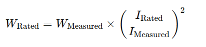
Since shunt reactors have a very low power factor, using a conventional wattmeter to measure losses can lead to inaccurate results. For improved precision, the bridge method is preferred.
It is important to note that this testing method does not separate losses in different components of the reactor. To ensure accurate results and account for temperature effects, the measurements should ideally be conducted when the average winding temperature matches the reference temperature. This helps correct the results and standardize them for comparison.
Applications of Shunt Reactors
Shunt reactors are widely used in electrical power systems for:
- Absorbing and compensating reactive power in transmission lines
- Voltage regulation during light-load conditions
- Improving system power factor
- Reducing transmission losses
- Enhancing stability of HV and EHV networks
- Protecting generators and transformers
- Reactive power compensation in substations
- Reducing electromagnetic interference in high-voltage systems
Conclusion
Shunt reactors are an essential component in modern electrical power systems, providing voltage stabilization and reactive power compensation across transmission and distribution networks. By absorbing excess reactive power, they help maintain a stable voltage profile, reduce line losses, improve system efficiency, and protect equipment such as transformers and generators from overvoltage stresses.
Both dry-type and oil-immersed shunt reactors have their specific applications depending on voltage levels and environmental conditions. While dry-type reactors are suitable for medium-voltage installations with simpler cooling requirements, oil-immersed reactors are preferred for high and extra-high voltage systems due to their superior insulation and cooling capabilities.
With the advancement of technology, variable shunt reactors (VSRs) now offer adjustable ratings to match fluctuating loads, providing flexible and precise control of reactive power in complex networks. Overall, the proper selection, installation, and maintenance of shunt reactors play a vital role in ensuring reliable, efficient, and stable operation of power transmission systems.
Read Next: