The stator of an induction motor consists of a number of overlapping windings offset by an electrical angle of 120°. When the primary winding or stator is connected to a three-phase alternating current supply, it establishes a rotating magnetic field in induction motor systems that rotates at a synchronous speed and enables efficient torque production.
What is Rotating Magentic Field(RMF) in Induction Motor?
This rotating magnetic field (RMF) is essential for inducing current in the rotor and initiating motion, making it the working principle behind every three-phase induction motor.
It forms due to the interaction of three-phase currents in stator windings placed 120° apart, resulting in a rotating field that drives the rotor through electromagnetic induction.
Three Phase Waveform and Positive Sequence
The waveform of the three fluxes is given below.
These waveforms represent the sinusoidal nature of each phase’s magnetic flux and are 120 degrees apart, creating the conditions needed for RMF formation.
How Rotating Magnetic Field is Produced
The 3-phase motor winding carries the balance current if the applied sinusoidal voltage is balanced and the impedance of each winding is also balanced. The stator winding is physically placed 120 electrical degrees apart, as shown in the figure below.
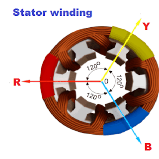
When balanced three-phase currents pass through the 3-phase motor winding spaced 120° apart, the time- and space-shifted magnetic fields combine to form a single rotating magnetic field.
Direction of Rotating Magnetic Field in Induction Motor
When a three-phase supply with a positive phase sequence (R-Y-B) is applied to the stator windings, the resulting magnetic field rotates in a specific direction—typically clockwise when viewed from the shaft end. The direction of rotation of the rotating magnetic field is directly determined by the order of the phase sequence.
If the phase sequence is reversed (R-B-Y), the direction of the magnetic field also reverses, causing the motor to rotate in the opposite direction.
This principle is often used to control the direction of rotation in three-phase motors simply by swapping any two supply lines.
Read detailed article on: What is a Phase Sequence & Its Significance
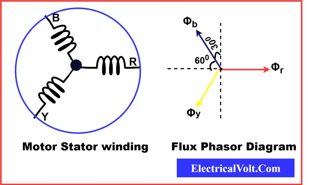
Phase Relationships and Magnetic Flux Interaction
If the phase sequence is R, Y, B, the Y phase current lags the R phase current by 120 degrees, and the B phase current lags the Y phase current by 120 degrees or leads the R phase current by 120 degrees.
The phase currents Ir, Iy, and Ib set up flux in the core. The resultant magnitude of the average flux can be calculated by adding the magnetic flux produced by individual currents.
The interaction of these time-shifted and spatially-separated phase currents produces a uniform rotating magnetic field in the stator.
Despite the continuous variation of individual phase fluxes, their vector sum remains constant in magnitude and rotates smoothly.
This magnetic field rotates at synchronous speed, which is determined by the supply frequency and the number of poles in the motor.
Flux Calculation in a Three-Phase Induction Motor
Let us first take the case when the R phase current is at the zero position of the waveform. The flux produced by the R phase current is Фr.
Фr = Фm sin(o°) = 0
Фy = Фm sin(0°-120°) =Фm sin(-120°) = – 0.866 Фm
Фb = Фm sin(0°-240°) =Фm sin(-240°) = 0.866 Фm
If we add the instantaneous value of the fluxes produced by phase voltages, the resultant flux in the motor
Фtotal = Фr + Фy + Фb
Фtotal = 0 − 0.866 Фm + 0.866 Фm =0
Although the instantaneous resultant is zero at this particular moment, as the phase currents continue to vary sinusoidally over time, their vector sum traces a circular path, forming a magnetic field of constant magnitude rotating at synchronous speed.
This confirms the principle already discussed: vector summation of balanced sinusoidal fluxes results in uniform rotation.
Over one complete cycle, this interaction results in an average resultant flux.
In a balanced three-phase system, the magnetic fluxes produced by the stator windings are equal in magnitude and 120° apart in both time and space. When added as vectors, these fluxes form a rotating field of constant amplitude.
By vector analysis, the magnitude of the resultant rotating flux is found to be:
Average Resultant Flux=1.5×Фm
Where, Фm is maximum flux
This relationship confirms that even though the individual phase fluxes vary, their combined effect produces a uniform rotating magnetic field — the core principle of RMF in an induction motor.
Mathematical Analysis of Rotating Magnetic Field
Consider three identical stator coils placed 120° apart in space and energized by a balanced three-phase AC supply. Each coil produces an alternating magnetic flux along its own axis.
Let the instantaneous fluxes in the r, y, and b phases be:
Фr = Фm sin(ωt) …(1)
Фy = Фm sin(ωt − 120°) …(2)
Фb = Фm sin(ωt + 120°) …(3)
Here, Фm is the maximum flux generated by each phase winding.
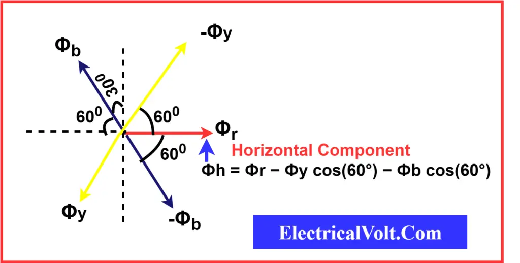
To determine the resultant magnetic field, we resolve each flux into horizontal and vertical components and compute their vector sum.
Horizontal Component of Flux
The horizontal component of the resultant flux is:
Фh = Фr − Фy cos(60°) − Фb cos(60°)
⇒ Фh = Фr − ½ (Фy + Фb)
Substitute equations (1), (2), and (3):
Фh = Фm sin(ωt) − ½ [Фm sin(ωt − 120°) + Фm sin(ωt + 120°)]
Using trigonometric identities:
Фh = Фm sin(ωt) − (Фm / 2) × [2 sin(ωt) cos(120°)]
⇒ Фh = Фm sin(ωt) − Фm sin(ωt) × (−½)
⇒ Фh = (3/2) Фm sin(ωt) …(4)
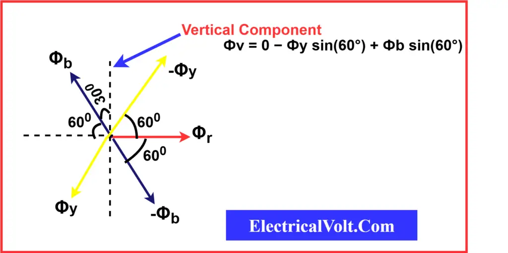
Vertical Component of Flux
The vertical component of the resultant flux is:
Фv = −Фy sin(60°) + Фb sin(60°)
⇒ Фv = (−Фy + Фb) sin(60°)
Substitute equations (2) and (3):
Фv = [−Фm sin(ωt − 120°) + Фm sin(ωt + 120°)] × (√3/2)
Using identities:
Фv = Фm × 2 cos(ωt) sin(120°) × (√3/2)
⇒ Фv = (3/2) Фm cos(ωt) …(5)
Magnitude of the Resultant Flux
The resultant flux is the vector sum of horizontal and vertical components:
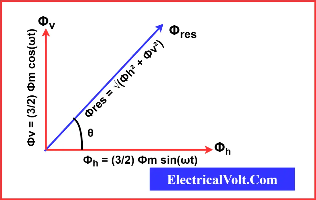
Фres = √(Фh² + Фv²)
= √[(3/2 Фm sin(ωt))² + (3/2 Фm cos(ωt))²]
= (3/2) Фm √(sin²(ωt) + cos²(ωt))
= (3/2) Фm …(6)
Hence, the magnitude of the resultant rotating magnetic field is constant and equal to 1.5 times the maximum flux in any one phase.
Direction of the Resultant Flux
The angle θ made by the resultant flux with the reference axis is:
tan(θ) = Фv / Фh
= (3/2 Фm cos(ωt)) / (3/2 Фm sin(ωt))
= cot(ωt)= tan(90° − ωt)
⇒ θ = 90° − ωt …(7)
This shows that θ varies with time, meaning the resultant magnetic field rotates continuously in space.
Rotational Behavior at Key Instants
- At ωt = 0°, θ = 90° → Position A
- At ωt = 90°, θ = 0° → Position B
- At ωt = 180°, θ = −90° → Position C
- At ωt = 270°, θ = −180° → Position D
Therefore, the resultant flux rotates clockwise with an angular velocity of ω radians/second.
Analysis of Rotating Magnetic Field at Different Time Instants
To understand the behavior of the rotating magnetic field in a three-phase induction motor, we analyze the resultant flux at different values of ωt using the flux equations:
To understand the behavior of the rotating magnetic field in a three-phase induction motor, we analyze the resultant flux at different values of ωt using the flux equations:
- Фr = Фm sin(ωt)
- Фy = Фm sin(ωt − 120°)
- Фb = Фm sin(ωt + 120°)
Case I – When ωt = 0°
This corresponds to the origin point on the waveform.
Substituting into the flux equations:
- Фr = Фm sin(0°) = 0
- Фy = Фm sin(−120°) = −(√3/2) Фm
- Фb = Фm sin(+120°) = (√3/2) Фm
Here, the fluxes Фy and Фb are equal in magnitude and opposite in direction. Their phasor sum results in a resultant flux along a direction 90° clockwise from the r-axis.
- Resultant flux: Фres = 2 × (√3/2 Фm) × cos(30°) = (3/2) Фm
Case II – When ωt = 60°
This corresponds to the next significant point on the waveform.
Substituting into the equations:
- Фr = Фm sin(60°) = (√3/2) Фm
- Фy = Фm sin(−60°) = −(√3/2) Фm
- Фb = Фm sin(180°) = 0
Now, Фr and Фy are again equal in magnitude and opposite in direction, rotated by 60° compared to Case I.
- Resultant flux: Фres = 2 × (√3/2 Фm) × cos(30°) = (3/2) Фm
Thus, the flux has rotated by 60° clockwise compared to Case I.
Case III – When ωt = 120°
At this instant:
- Фr = Фm sin(120°) = (√3/2) Фm
- Фy = Фm sin(0°) = 0
- Фb = Фm sin(240°) = −(√3/2) Фm
Once again, the net flux is the result of two equal and opposite phasors, rotated an additional 60°.
- Resultant flux: Фres = 2 × (√3/2 Фm) × cos(30°) = (3/2) Фm
The resultant flux has now rotated 120° clockwise from its initial position.
Case IV – When ωt = 180°
Substituting:
- Фr = Фm sin(180°) = 0
- Фy = Фm sin(60°) = (√3/2) Фm
- Фb = Фm sin(300°) = −(√3/2) Фm
Here too, the phasors are equal and opposite, with the resultant flux rotating another 60°.
- Resultant flux: Фres = 2 × (√3/2 Фm) × cos(30°) = (3/2) Фm
The net rotation is now 180° clockwise from the starting point.
From the above analysis, we can conclude the following:
- A balanced 3-phase AC supply produces a rotating magnetic field of constant magnitude.
- The magnitude of this resultant flux is always:
- Фres = (3/2) Фm
- i.e., 1.5 times the maximum flux produced by any one phase.
- The flux rotates at a uniform angular velocity, equal to that of the supply frequency:
- ω = 2πf radians/second
- The direction of rotation of the magnetic field depends on the phase sequence of the 3-phase supply. Reversing the phase sequence reverses the direction of rotation.
Synchronous Speed of Rotating Magnetic Field
The magnetic field rotates at a synchronous speed given by:
Ns = (120 × f) / P
Where:
Ns = Synchronous speed in RPM
f = Frequency in Hz
P = Number of poles
This formula explains how the speed of the rotating magnetic field is related to the supply frequency and number of poles in the motor.
Conclusion: Working Principle of RMF in Induction Motor
In conclusion, the rotating magnetic field in a 3-phase induction motor ensures efficient torque production and smooth motor operation under varying load conditions with minimal vibrations.
It is formed by the interaction of sinusoidal currents flowing through stator windings placed 120° apart, resulting in a magnetic field of constant magnitude rotating at synchronous speed.
This principle lies at the heart of the robust and reliable performance of three-phase induction motors used in both industrial and domestic applications.
Related Articles:
2 thoughts on “Rotating Magnetic Field in a 3-Phase Induction Motor”