Foundation Fieldbus is an all-digital, serial, two-way, multi-drop industrial communication system operating at 31.25 kbit/s (H1 level). It functions as the base-level network in plant automation systems.
It has an open architecture developed and maintained by FieldComm Group. Foundation Fieldbus connects intelligent field equipment such as smart transmitters, control valve positioners, and controllers.
Unlike traditional 4–20 mA systems that transmit only one variable per loop, Foundation Fieldbus allows multiple process variables, advanced diagnostics, and communication over a single twisted-pair cable.
It is widely used in process industries, oil & gas plants, petrochemical plants, and power plants.
There are two types of Foundation Fieldbus based on physical media and communication speed.
Types of Foundation Fieldbus
There are two types:
- Foundation Fieldbus H1
- Foundation Fieldbus HSE (High-Speed Ethernet)
Foundation Fieldbus H1
Foundation Fieldbus H1 operates at 31.25 kbit/s. It connects field devices to host systems and provides both power and communication over a single twisted pair cable.
Although up to 32 devices can be connected per segment (as per standard), practical engineering design typically limits this to 10–12 devices to ensure proper voltage margin and spare capacity.
Foundation Fieldbus HSE (High-Speed Ethernet)
HSE operates at 100/1000 Mbit/s. It connects host systems, linking devices, and gateways at the control and backbone level.
Unlike H1, HSE does not provide power over cable and uses standard Ethernet infrastructure.
FOUNDATION Fieldbus H1 Architecture
H1 refers to a FOUNDATION Fieldbus network operating at a communication speed of 31.25 kbit/s and is widely applied in process automation systems. FOUNDATION Fieldbus H1 networks are organized into physical sections known as segments.
A segment is a defined section of an H1 fieldbus network that is terminated at both ends with the proper characteristic impedance. Multiple segments may be interconnected through repeaters to form an extended H1 network. Each individual segment can technically support up to 32 H1-compatible devices, subject to engineering and power constraints.
In practical usage, a segment consists of the trunk cable, spur cables, two terminators, a fieldbus power supply, and the connected field devices installed between the terminators. Although official FOUNDATION Fieldbus documentation distinguishes between a “segment” (physical layer) and a “network” (entire device system), industry practice frequently uses these terms interchangeably. Two terminators are mandatory on every segment to ensure proper signal integrity.
For a fully populated 31.25 kbit/s voltage-mode fieldbus segment, the maximum total cable length—including trunk and all spurs—between any two devices can reach 1,900 meters. In accordance with IEC 61158-2, the maximum trunk length is 1,200 meters, and the maximum spur length is 120 meters.
However, project design standards often impose stricter limits. The recommended maximum number of devices per segment, including allowances for future additions, should not exceed 12 devices. A minimum spare capacity of 20% is typically required.
For example:
If a segment is designed for a maximum of 12 devices,
Only 10 devices should be installed initially,
Leaving capacity for at least 2 additional future devices.
This reserved capacity allows for expansion, such as adding one complete control loop (for example, one transmitter and one final control element). Accordingly, each segment should be engineered to accommodate at least two future devices.
In addition to device count, 20% spare current capacity must also be factored into the power design to support future expansion.
Most FOUNDATION Fieldbus instruments receive power directly from the bus. The DC supply voltage typically ranges from 9 VDC to 32 VDC.
Communication is achieved by superimposing a signal onto the DC supply. The transmitting device delivers ±10 mA into an equivalent 50-ohm load, creating approximately 1.0 V peak-to-peak signal voltage modulated over the DC power line.
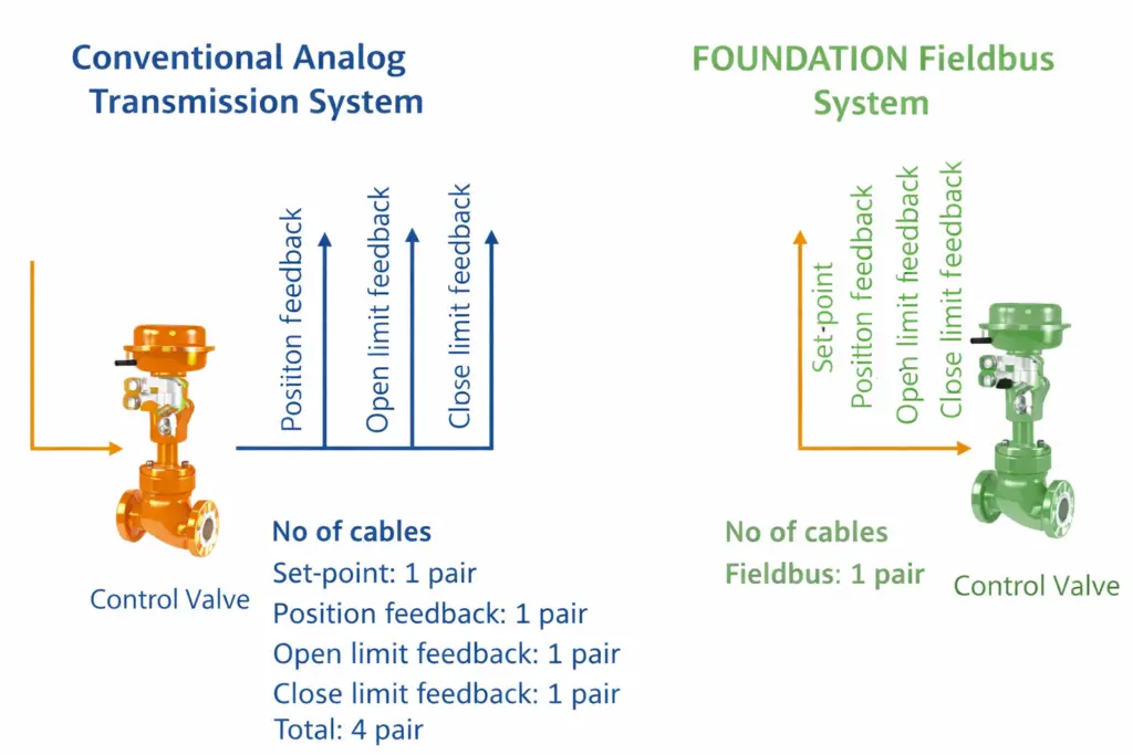
Analog Transmission vs Foundation Fieldbus
In a 4–20 mA analog system:
- One device per cable pair
- Limited diagnostics
- Control executed only in DCS
In Foundation Fieldbus:
- Multiple devices per cable
- Advanced diagnostics
- Distributed control in field devices
- Reduced wiring and cabinet space
Fieldbus Standard Specifications
Fieldbus communication systems are defined under IEC 61158-2 and ISA S50.02. These standards establish two categories of physical layer implementation: low-speed fieldbus and high-speed fieldbus. In addition, High Speed Ethernet (HSE) was introduced as an expanded communication option to support higher bandwidth requirements.
The physical fieldbus architecture is therefore divided into two primary types: Low-Speed Fieldbus (FF-H1) and High-Speed Fieldbus (FF-HSE).
Low-Speed Fieldbus (FF-H1) operates at a transmission rate of 31.25 kbps. Each segment can support up to 32 devices, depending on power and design limitations. Communication typically uses shielded twisted pair cable, although optical fiber may also be applied in certain configurations.
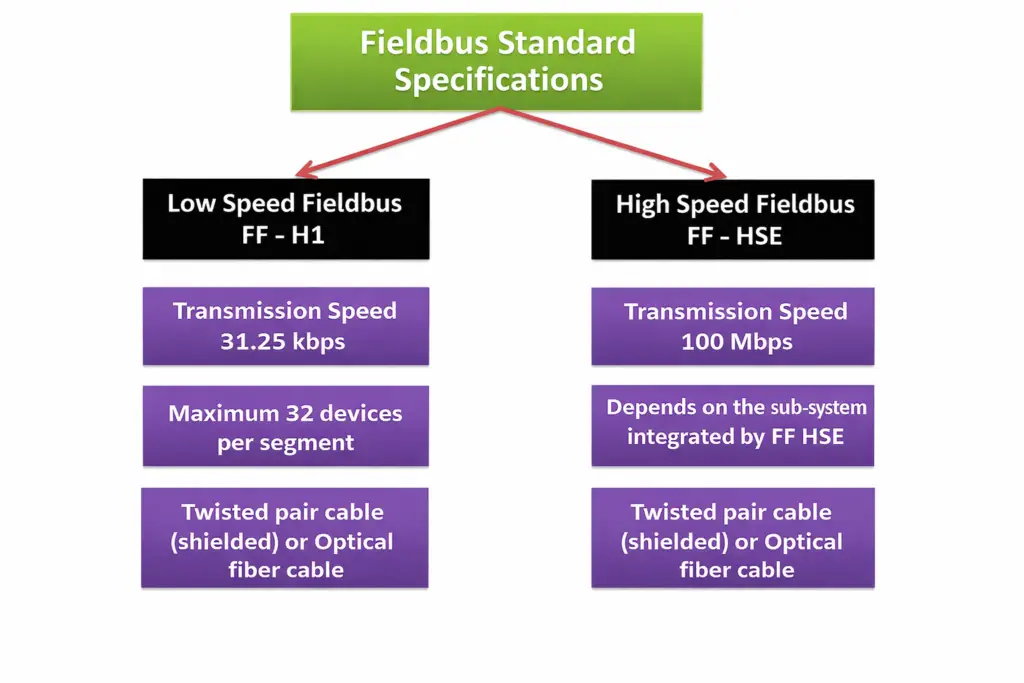
High-Speed Fieldbus (FF-HSE) provides significantly higher data throughput, operating at 100 Mbps. This implementation is Ethernet-based and is commonly used for linking subsystems, controllers, and host systems through an FF-HSE integrated architecture. Similar to FF-H1, shielded twisted pair cable or optical fiber cable can be used as the transmission medium.
In fieldbus terminology, the term multivariable refers to multiple measured process parameters. Multivariable sensing describes the ability of a single field device to detect and transmit more than one process variable at the same time.
Advantages of FOUNDATION Fieldbus
FOUNDATION Fieldbus offers several technical and operational benefits compared to conventional analog systems:
- Reduced cabling and hardware requirements – Fewer field wires, marshaling panels, intrinsic safety barriers, I/O cards, and separate power supplies are required due to digital multidrop architecture.
- Smaller equipment room footprint – With less termination and interface hardware, control and equipment rooms can be significantly downsized.
- Remote configuration capability – Field devices can be configured, calibrated, and monitored remotely from the control system without physical access.
- Enhanced operational data availability – Digital communication enables access to detailed process variables, status parameters, and device health information for operations and maintenance teams.
- Improved measurement precision – Digital signal transmission minimizes signal degradation and noise, leading to higher measurement accuracy.
- Higher plant availability – Faster commissioning and simplified troubleshooting contribute to increased system uptime.
- Advanced diagnostics – Built-in self-diagnostics and remote diagnostic functions allow early detection of faults, reducing unexpected failures and maintenance costs.
Limitations of FOUNDATION Fieldbus
FOUNDATION Fieldbus has certain limitations that should be considered during system selection and design:
- Not suitable for very fast control applications – Systems requiring extremely fast response times (approximately 200 milliseconds or less), such as anti-surge control, are not ideal for standard H1 fieldbus implementation.
- Common point of failure risk – Multiple field devices are typically connected through a single field barrier or power conditioner; if this component fails, several connected instruments may be affected simultaneously.
- Higher engineering complexity – Segment design, power calculations, communication scheduling, and device configuration require more detailed planning compared to conventional analog systems.
- Specialized troubleshooting requirements – Diagnosing communication or segment-related issues may require trained personnel and dedicated fieldbus diagnostic tools.
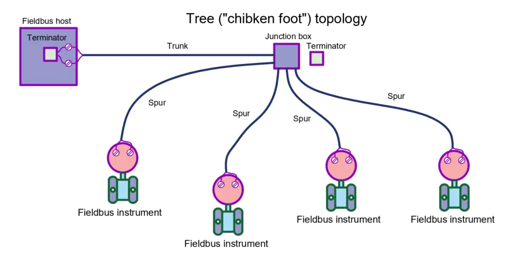
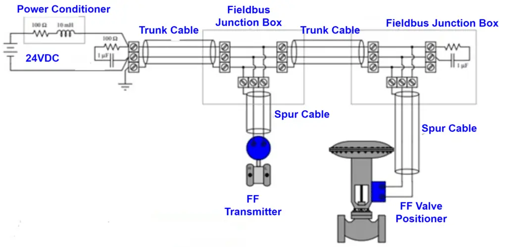
FOUNDATION Fieldbus Topologies and Cabling Arrangement
FOUNDATION Fieldbus networks can be arranged in several physical configurations, with the tree topology being one of the most commonly applied in plant installations.
In a typical tree layout, multi-pair trunk cables (commonly 5-pair) are routed from the marshalling cabinets to intermediate junction boxes located in different plant areas. This approach significantly reduces the number of individual fieldbus cables entering the Panel Building, resulting in lower installation costs and simplified cable management. These multi-pair trunk cables are dedicated exclusively to FOUNDATION Fieldbus signals.
From the Intermediate Junction Box, each segment normally continues via a multi-pair trunk (H1) cable toward FOUNDATION Fieldbus junction boxes. The multi-pair cable connects the Intermediate FF Junction Box to the marshalling cabinet, while single-pair cables are used between the Intermediate FF Junction Box and the Spur Junction Boxes.
The FOUNDATION Fieldbus Spur Junction Boxes are typically designed in a split configuration. One side accommodates the high-power, non-intrinsically safe (Non-IS) trunk connections, while the other side houses the fieldbus barriers, surge protection devices, and terminals for intrinsically safe (IS) connections in hazardous areas.
For non-hazardous areas, fieldbus barriers and the split junction box configuration are not required. Instead, a wiring hub such as a Mega Block can be used. In Non-IS zones, a Mega Block junction box replaces the spur junction box that would otherwise be required for intrinsically safe installations.
FOUNDATION Fieldbus Cable Requirements
In a typical installation, a 5-pair trunk cable is routed from the marshaling cabinet to an intermediate junction box located in the field. Out of these five pairs, one pair is normally reserved as a spare, while the remaining four pairs are used to connect four separate spur junction boxes equipped with field barriers. Each barrier then connects to individual field devices using single-pair spur cables. This arrangement improves cable management and reduces the number of direct home-run cables to the control building.
H1 Spur Cable Requirements
All H1 spur cables must be Type A cables as specified in IEC 61158-2. These consist of a single twisted pair with an overall shield and must also comply with the FF-844 (H1 cable test specification).
For intrinsically safe (IS) installations:
- H1 spur cables shall be 1 mm² IS single-pair cables for field instruments.
- For Temperature Multiplexer junction boxes containing two multiplexer devices, two-pair 1 mm² IS cables are required.
- Where only a single multiplexer is used, one pair of 1 mm² IS cable is sufficient.
H1 Trunk Cable Requirements
H1 trunk cables shall consist of multiple twisted pairs with both individual pair shielding and an overall shield. Electrically, trunk cables must meet the Type A cable parameters defined in IEC 61158-2.
- H1 trunk cables are typically 1.5 mm² Non-IS for trunk lengths up to 1000 meters.
Cable Length Limitations
The maximum allowable cable lengths for a FOUNDATION Fieldbus segment are:
- Total segment length (trunk + all spurs): 1900 meters
- Maximum trunk length: 1200 meters
- Maximum spur length: 120 meters (depending on barrier design)
Specifications of FOUNDATION Fieldbus Cable Types
Due to the specific signal levels used in FOUNDATION Fieldbus communication, cable characteristics are critical for reliable data transmission. Four cable types are defined: Type A, Type B, Type C, and Type D. Among these, Type A is the preferred and most widely used cable type.
a) Type A Fieldbus Cable
Type A cable uses 18 AWG (approximately 0.8 mm) twisted pair conductors with an overall shield. The twisted pair construction minimizes noise interference, and the shield further enhances signal protection.
Typical characteristics:
- Conductor size: 18 AWG (0.8 mm)
- Shield coverage: 90%
- Attenuation: 3 dB/km at 39 kHz
- Characteristic impedance: 100 Ω ±20% at 31.25 kHz
- Maximum segment length: 1900 meters
Type A cable is the most suitable and commonly specified cable for FOUNDATION Fieldbus installations.
b) Type B Fieldbus Cable
Type B cable consists of multiple shielded pairs of 22 AWG conductors. It provides a characteristic impedance of 100 Ω at 31.25 kbps.
However, due to its smaller conductor size, it has higher electrical resistance, which limits performance.
- Maximum network length: 1200 meters
c) Type C Fieldbus Cable
Type C cable consists of multiple unshielded pairs of 26 AWG conductors.
- Maximum allowable length: 400 meters
Because it lacks shielding, it is generally not recommended for FOUNDATION Fieldbus applications.
d) Type D Fieldbus Cable
Type D cable is a multicore, unshielded, untwisted 16 AWG cable.
- Maximum allowable length: 200 meters
This cable type is also not preferred for FOUNDATION Fieldbus systems due to the absence of twisting and shielding, which are critical for noise immunity.
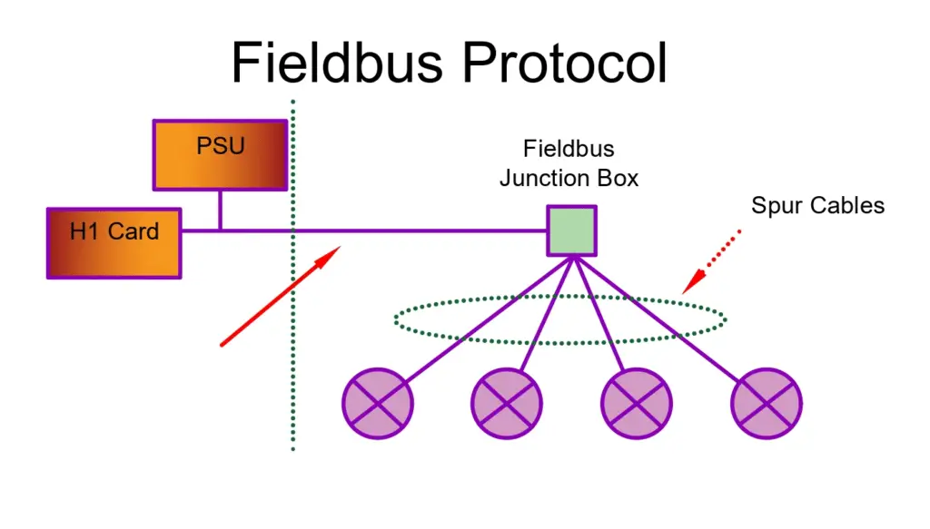
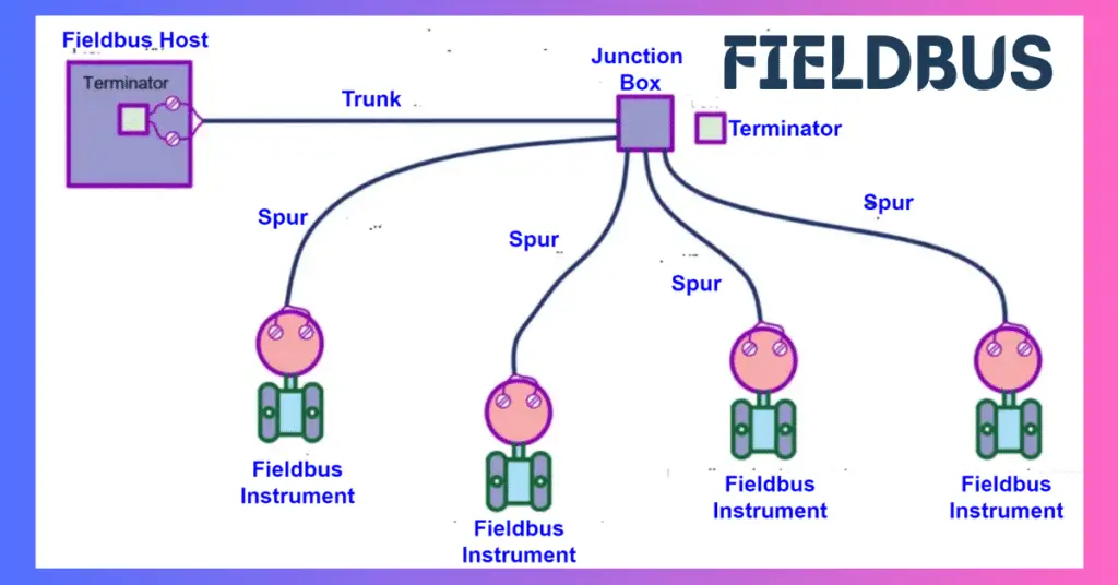
Components of Foundation Fieldbus
A standard Foundation Fieldbus segment typically includes the following components:
- H1 Card – The fieldbus interface card connecting the segment to the control system. Redundant H1 cards are often implemented depending on the application requirements.
- Power Supply (PS) – Provides bulk DC power to the Fieldbus Power Supply (FPS).
- Fieldbus Power Supply & Signal Conditioner (FPS) – Supplies regulated power to the segment and conditions the signal. Modern installations often use integrated FPS units.
- Terminators (T) – Two terminators are required per segment: one at the FPS and one at the farthest device coupler, ensuring proper signal integrity.
- Linking Device (LD) – Used primarily in HSE networks to connect 4–8 H1 segments to an HSE backbone, acting as a gateway.
- Fieldbus Devices – Includes smart field instruments such as transmitters, actuators, and transducers that communicate over the segment.
Earthing Scheme in Foundation Fieldbus
A proper earthing (grounding) scheme is essential for maintaining reliable communication in a Foundation Fieldbus H1 segment. Since the protocol operates at low millivolt signal levels, it is highly sensitive to electrical disturbances such as electromagnetic interference (EMI), electrostatic induction, radio frequency interference (RFI), and ground potential differences. Without a well-designed grounding system, these disturbances can degrade signal quality and lead to communication instability.
In a Foundation Fieldbus network, the two signal conductors are preserved as a differential pair throughout the segment. Grounding either conductor will interrupt communication for all devices on that segment. Therefore, only the cable shield — not the signal cores — is grounded, and this must be done at a single designated point to prevent ground loops.
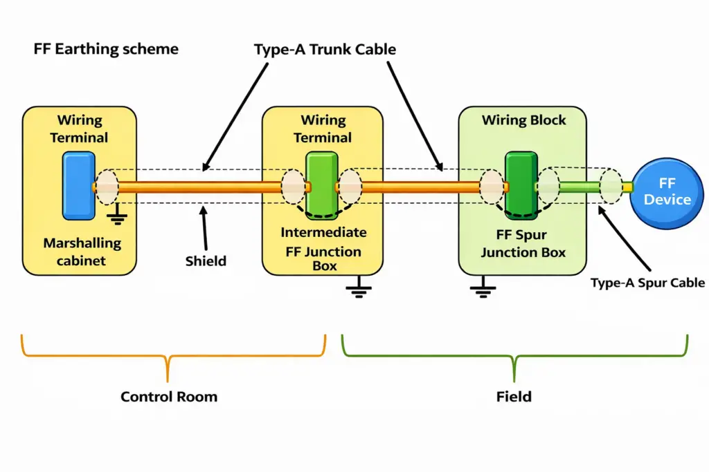
The standard grounding philosophy is based on single-point shield grounding. For multi-pair trunk cables, the shield is terminated and grounded only at the DCS end in the marshalling cabinet. It must not be grounded anywhere else along the segment. For single-pair trunk cables, the shield is connected to the multi-pair trunk shield at the intermediate Fieldbus junction box, without introducing additional grounding points.
Spur cable shields are connected to the trunk shield inside the FF Spur Junction Box and remain unconnected at the field device end. The shield at the device side must be insulated using heat shrink or a protective sleeve to prevent accidental grounding. Importantly, no connection is made between trunk or spur shields and the metallic body of the junction box.
While signal shields follow a single-point grounding approach, the safety (case) grounding of field devices and junction boxes must be connected locally to protective earth. Additionally, shields from different Fieldbus segments must never be interconnected, as this can create unwanted circulating currents and noise issues.
Proper termination is another key part of the earthing scheme. Each Foundation Fieldbus segment must have exactly two terminators: one at the DCS side (typically integrated within the Fieldbus power supply and enabled via jumper or dip switch) and one at the farthest end of the trunk, usually inside the FF Spur Junction Box. Terminators must not be installed inside Fieldbus devices.
Surge protection is required to protect the segment from transient overvoltages. Trunk cables should have surge protection at both ends — at the marshalling cabinet and at the field junction box. In areas with high lightning exposure, such as tank farms or open process units, individual instrument surge protection should also be considered. Surge protection devices must be connected to the local protective earth.
For hazardous areas, all Foundation Fieldbus devices must comply with project certification requirements and be certified as Intrinsically Safe (FISCO compliant). Many installations use a High Power Trunk “Hybrid” concept, where the trunk is protected using the Increased Safety (Ex e) method, while intrinsically safe spurs are created using Fieldbus barriers that limit voltage and current to the field devices. This design allows energized maintenance in hazardous areas while maintaining safety compliance.
In non-hazardous areas, Fieldbus barriers are not required, and a standard wiring hub can be used. These hubs provide individual spur isolation so that a fault in one device does not affect the entire segment.
A correctly implemented earthing scheme ensures noise immunity, prevents ground loops, protects against lightning damage, and maintains stable communication across the Foundation Fieldbus network.
Signal Strength in Foundation Fieldbus
In a Foundation Fieldbus network, signal strength is predefined and must remain within specified limits for reliable communication. If the signal level deviates from the acceptable range, communication issues may occur.
Signal strength can decrease due to:
- Electrical noise
- Excessive terminators in the loop
- Cable faults
- Device circuit problems
Signal strength can also increase, which is not acceptable. This typically happens due to:
- A missing terminator
- A faulty terminator
- Fewer than the required number of terminators
To maintain proper operation, always ensure exactly two terminators are installed—one at each end of the trunk line.
Acceptable Signal Voltage Levels (Peak-to-Peak)
| Signal Level (mV p-p) | Interpretation |
| > 800 mV | Missing or faulty terminator |
| 350–700 mV | Excellent signal strength |
| 150–350 mV | Marginal signal level (possible extra terminator) |
| < 150 mV | Signal too low – communication failure |
Maintaining the signal within the 350–700 mV range ensures stable and reliable Foundation Fieldbus communication.
Noise Level in Foundation Fieldbus
Since the Foundation Fieldbus protocol operates at millivolt signal levels, noise has a significant impact on communication quality. When noise remains below a certain threshold, it does not affect the signal. However, once it exceeds acceptable limits, signal quality begins to deteriorate, leading to unstable communication and device issues.
For reliable operation, the noise level must remain below 50 mV peak-to-peak (pk-pk). Noise is measured in millivolts (pk-pk), and its interpretation is as follows:
| Noise Level (mV pk-pk) | Interpretation |
| < 25 mV | Excellent |
| 25–50 mV | Acceptable |
| 50–100 mV | Marginal |
| > 100 mV | Poor |
This is why noise measurement is an essential troubleshooting step whenever communication problems or device faults occur in a Foundation Fieldbus network.
Proper cable shielding plays a crucial role in minimizing noise. For this reason, Fieldbus Type-A cable is commonly used, as it provides effective shielding and helps maintain stable signal integrity.
Jitter in Foundation Fieldbus Protocol
Jitter measurement is an advanced and highly accurate diagnostic method used to evaluate the health of a Foundation Fieldbus segment. It is particularly effective in identifying developing faults before a complete communication failure occurs.
Leading organizations such as MTL Instruments, Pepperl+Fuchs, Relcom Inc., Chevron, Emerson Electric, and Yokogawa Electric Corporation recognize jitter as a valuable parameter for analyzing network impedance, segment loading, and power supply performance.
Jitter measurement is also the only parameter that confirms a fieldbus power supply’s compliance with IEC 61158-2 and verifies performance according to the FF-831 Fieldbus power supply test specification. This ensures proper compatibility between the power supply and connected field devices.
A key advantage of jitter analysis is that it ignores the individual effects of noise, attenuation, and distortion, and instead evaluates their combined impact on communication timing. For example, these parameters may remain within acceptable limits and not trigger alarms individually. However, collectively they can still cause data detection failure.
Here, jitter helps detect early-stage degradation before any other parameter provides an indication.
Key Benefits of Jitter Measurement
- Evaluates overall segment health
- Detects power supply instability
- Identifies impedance mismatch and improper loading
- Predicts communication failure before it occurs
Because of this strong predictive capability, jitter measurement is considered one of the most powerful diagnostic tools in Foundation Fieldbus networks.
Foundation Fieldbus vs Profibus
| Feature | Foundation Fieldbus (FF) | PROFIBUS |
| Type | All-digital, serial, multidrop, two-way communication | Digital fieldbus for process and factory automation |
| Communication | Peer-to-peer; distributed control | Master-slave; centralized control |
| Speed | H1: 31.25 kbps; HSE: 100/1000 Mbps | DP: up to 12 Mbps; PA: 31.25 kbps |
| Power over Bus | Yes, H1 supports power to devices | DP: No; PA: limited power to devices |
| Number of Variables | Multiple process variables per device | Typically one variable per device |
| Diagnostics | Advanced device diagnostics and jitter analysis | Basic device status and error codes |
| Topology | Trunk-and-spur, tree, or star | Line, tree, or star; repeaters often needed |
| Applications | Process industries: oil & gas, petrochemical, power plants | Factory automation, discrete and process automation |
| Advantages | Reduced wiring, distributed control, advanced diagnostics | Simpler setup, faster for discrete automation, widely adopted |
| Limitations | Slower for ultra-fast loops; higher engineering complexity | Master-slave limits distributed control; slower diagnostics in PA |
Conclusion
Foundation Fieldbus is a reliable digital communication system that enables multiple devices and process variables over a single network. With H1 for field-level communication and HSE for high-speed backbone integration, it supports distributed control, advanced diagnostics, and reduced wiring.
Proper earthing, terminator placement, surge protection, and noise management, along with jitter measurement, ensure stable and reliable operation. Despite its complexity and limitations in ultra-fast control, Foundation Fieldbus remains a preferred solution in process, oil & gas, petrochemical, and power industries for enhanced efficiency, accuracy, and safety.
Read Next: