Why DC Series Motor should not be Started at No Load
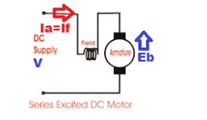
The DC series motor attains dangerously high speed when we run it on no load. The main reason for overspeeding is that at no load,
An electrical machine converts mechanical energy into electrical energy or vice versa. The transformer is also an electrical machine which transform the voltage without changing the frequency. We will discuss about the;
The DC series motor attains dangerously high speed when we run it on no load. The main reason for overspeeding is that at no load,
Why star delta starter is preferred with induction motor can be understood from the following explanation. In star delta starting, the phase voltage is 58%
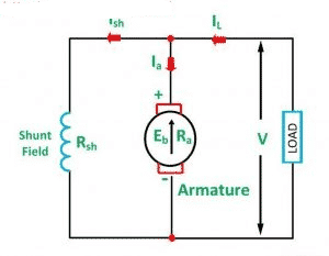
A DC shunt motor is known for its nearly constant speed operation, making it ideal for applications like lathes, fans, and conveyors. In this post,
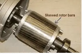
What is Skewing of Rotor Slots? As shown in the above picture, the rotor bars of an induction motor are not parallel with the shaft,
A star delta starter is a widely used method for reducing the inrush current when starting a three-phase induction motor. In this article, we’ll explore
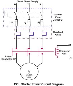
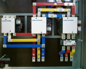
Direct online starter is a method of starting an induction motor. The stator of the motor receives the full supply voltage in the DOL starter.

A DC series motor is widely used for driving heavy loads due to its unique ability to produce very high starting torque. This article explains

💡 Key learnings: BDV Full Form: BDV stands for Breakdown Voltage, the maximum voltage transformer oil can withstand without breakdown. Importance of BDV Testing: Regular
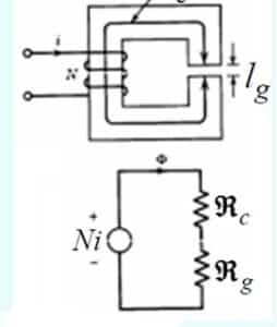
The air gap in an induction motor—the small physical distance between the stator and the rotor—has a major impact on the machine’s performance. Although it
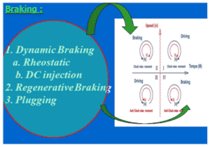
DC Injection Braking of Induction Motor is an effective method for stopping motors quickly without mechanical components. It involves applying DC to the stator windings