- Ohmmeter Definition: An ohmmeter is a device used to measure the resistance of circuits, components, or conductive paths, showing how much a material opposes electric current.
- Series Type Ohmmeter: Measures resistance by connecting the unknown resistor in series with the meter, adjusting current, and reading pointer deflection; ideal for medium resistance measurements.
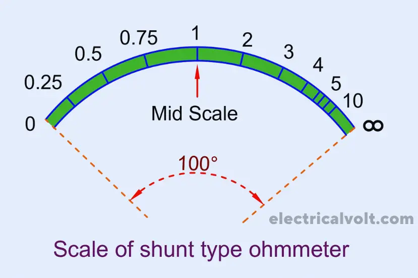
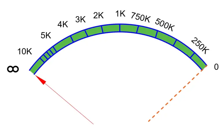
- Shunt Type Ohmmeter: Measures low resistance by connecting the meter in parallel with the resistor; current flow is adjusted for accurate readings with an inverted scale.
- Multi-Range Ohmmeter: Uses a range selector switch to measure resistance across various ranges, from very low to very high, offering versatility and precise measurements.
- Micro-Ohmmeter: Designed for extremely low resistances (µΩ to mΩ), commonly used for transformer windings, busbars, and motor terminals requiring high accuracy.
- Mega-Ohmmeter (Megger): Measures high and insulation resistance by applying high DC voltage; essential for motors, generators, transformers, and cable insulation testing.
- D’Arsonval Movement: Analog ohmmeters often use this mechanism, where a current-carrying coil in a magnetic field moves the pointer, providing accurate, linear, and low-power measurements.
- Proper Usage Practices: Includes discharging capacitors, zero-adjusting analog meters, and avoiding live circuits to ensure safe operation and precise readings.
- Applications Awareness: Used for continuity testing, troubleshooting faults, PCB fault detection, measuring motor winding resistance, testing heating elements, and preventive maintenance in electrical systems.
An ohmmeter is an electrical measuring instrument used to determine the resistance of a circuit, component, or electrical path. Resistance is the property of a material that opposes the flow of electric current and is measured in ohms (Ω).
Ohmmeters are widely used in electrical testing, troubleshooting, maintenance, and electronics laboratories to check continuity, detect faults, and verify component health.
What is an Ohmmeter?
An ohmmeter is an electrical measuring instrument used to determine the resistance of a circuit or individual component, where resistance is the property that opposes the flow of electric current and is measured in ohms (Ω).
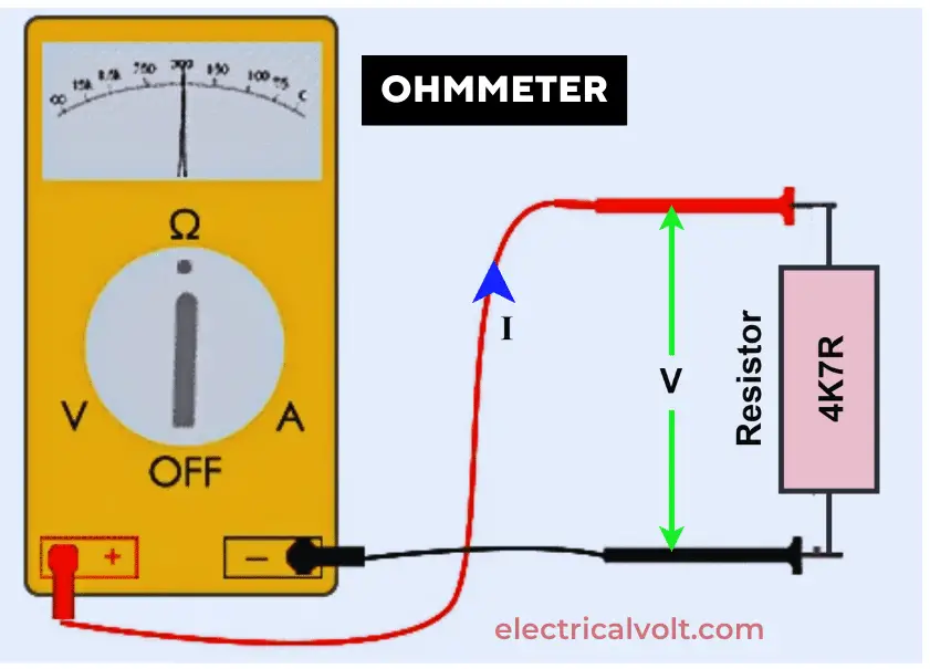
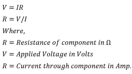
To measure resistance, the ohmmeter applies a small internal voltage across the test object and measures the resulting current. The resistance value is then calculated using Ohm’s law (R = V / I) and displayed on the meter.
Almost all materials exhibit resistance except superconductors. Materials with high electrical conductivity, such as metals, offer low resistance, whereas insulating materials exhibit very high resistance.
Semiconductors fall between these two categories, with resistance values that change depending on temperature and operating conditions. Since resistance values can range from micro-ohms to giga-ohms, ohmmeters are designed with different sensitivity levels to accurately measure low, medium, and high resistance values.
Working Principle of an Ohmmeter
The working principle of an ohmmeter is based on Ohm’s law, which states that resistance is the ratio of applied voltage to the resulting current. An ohmmeter contains an internal battery that supplies a small DC voltage to the component or circuit whose resistance is being measured.
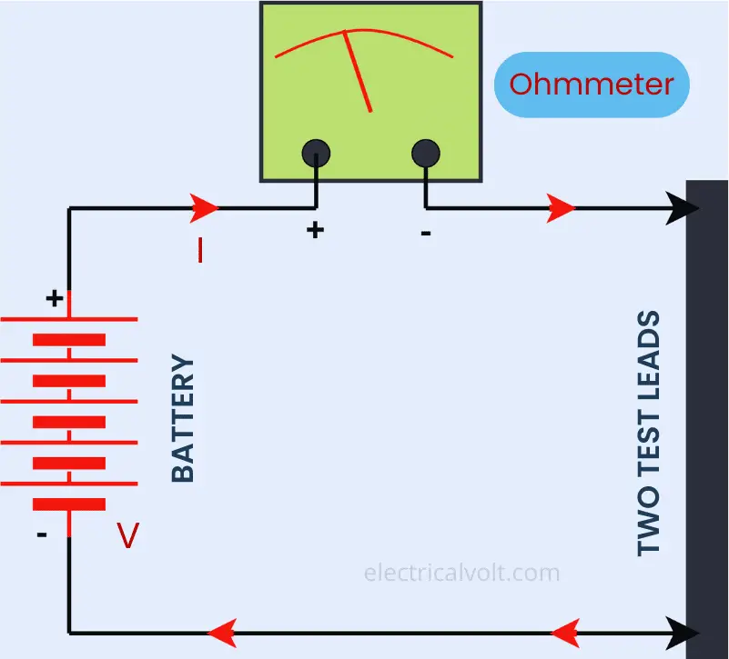
When the test leads are connected, the ohmmeter is placed in series with the component under test. The applied voltage causes current to flow through the component, and the magnitude of this current depends on the resistance value. The instrument’s internal circuitry measures the current and automatically calculates the resistance using the ohm’s law relation R = V / I. The measured resistance is then displayed on an analog scale or digital screen.
In analog ohmmeters, the measurement is performed using a D’Arsonval (PMMC) movement, which consists of a current-carrying coil placed in a magnetic field. As current flows through the coil, a deflecting torque is produced, causing the pointer to move and indicate the resistance value.
⚠️ Important:
An ohmmeter must never be connected to a live circuit, as external voltage can damage the instrument.
Working of D’Arsonval Movement
The D’Arsonval movement consists of a lightweight current-carrying coil placed within the magnetic field of a permanent magnet. When the ohmmeter is connected in series with a component and the internal battery is switched on, current flows through the coil and produces its own magnetic field.

The interaction between this magnetic field and the permanent magnet’s field generates a deflecting torque, causing the coil to rotate about its axis and move the pointer across the scale.
The amount of pointer deflection is directly proportional to the current flowing through the coil. If the circuit under test is open, no current flows, resulting in zero deflection, and the meter indicates infinite resistance (∞). As the resistance decreases, the current increases, and the pointer moves from the infinity side toward the zero-resistance end of the scale.
Key Features of D’Arsonval Movement
- Linear and uniform scale
- High sensitivity and accuracy
- Low power consumption
- Effective damping
- Suitable for DC measurements only
Because of its precision and stability, the D’Arsonval movement is widely used in analog ohmmeters and other DC measuring instruments.
Types of Ohmmeters Based on Resistance Range
1. Micro-Ohmmeter
A micro-ohmmeter is a highly sensitive resistance-measuring instrument designed to measure very low resistance values in the micro-ohm (µΩ) and milli-ohm (mΩ) range. Unlike conventional ohmmeters, which measure resistance from a few ohms to mega-ohms, micro-ohmmeters are specifically used where extremely small resistance values must be measured with high accuracy.
Applications of Micro-Ohmmeter
- Transformer winding resistance measurement
- Circuit breaker and switch contacts
- Busbars, joints, and bonding points
- Motor and generator terminals
2. Mega-Ohmmeter (Megger)
A mega-ohmmeter, commonly known as a megger, is a specialized electrical instrument used to measure very high resistance values, primarily the insulation resistance of electrical equipment. Unlike conventional ohmmeters, which operate in the ohm to mega-ohm range, mega-ohmmeters are designed to measure resistance values from mega-ohms (MΩ) up to giga-ohms (GΩ).
Applications of Mega-Ohmmeter
- Insulation testing of power and control cables
- Testing motors, generators, and transformers
- High-voltage electrical equipment and installations
Because of its ability to detect insulation deterioration, a mega-ohmmeter is an essential tool in electrical maintenance, safety testing, and preventive diagnostics.
Types of Ohmmeters Based on Circuit Configuration
1. Series Type Ohmmeter
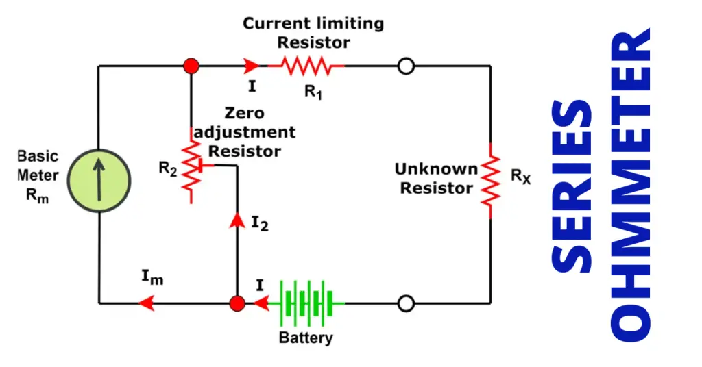
A series type ohmmeter is an analog resistance-measuring instrument in which the unknown resistance is connected in series with the meter movement. This configuration is commonly used for measuring medium resistance values. The circuit diagram of series type ohmmeter is shown below.
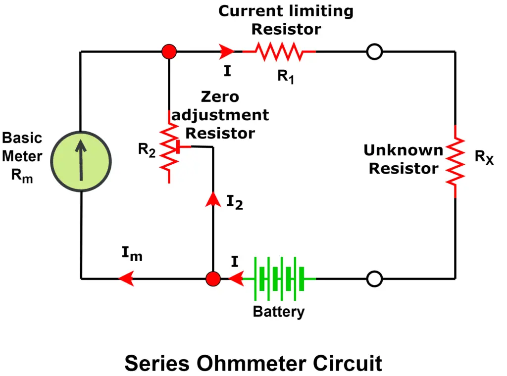
The zero-adjustment resistor is used to calibrate the meter and compensate for battery voltage variations.
Working of Series Ohmmeter
In a series type ohmmeter, the unknown resistance is placed in series with the measuring circuit, which is why it is known as a series ohmmeter. A zero-adjustment resistor (R₂) is provided to calibrate the meter and set the correct zero reading before measurement. The resistance values are indicated on a non-linear scale calibrated according to the meter’s operating characteristics.
Zero Resistance Condition (A–B Shorted):
When the test terminals are shorted, the unknown resistance becomes zero. In this condition, the circuit current is maximum, causing full-scale deflection of the pointer. The meter is adjusted using the zero-adjustment resistor so that this deflection corresponds to zero resistance, which is marked on the right side of the scale.

Infinite Resistance Condition (A–B Open):
When the test terminals are open, the circuit is incomplete and no current flows through the meter. As a result, there is no pointer deflection, and the meter indicates infinite resistance (∞) on the left side of the scale.
For resistance values between zero and infinity, the pointer deflects proportionally, allowing the resistance to be read directly from the non-linear scale.
Key Characteristics of Series Ohmmeter
- Zero resistance → Maximum current → Full-scale deflection
- Infinite resistance → Zero current → No deflection
- Non-linear resistance scale
- Zero marked on the right side of the scale
Because of its simplicity and reliability, the series type ohmmeter is widely used for measuring moderate resistance values in electrical testing and troubleshooting.
2. Shunt Type Ohmmeter
In a shunt-type ohmmeter, the unknown resistance is connected in parallel with the meter movement, making this configuration suitable for measuring low resistance values. The scale arrangement of a shunt ohmmeter is opposite to that of a series ohmmeter. The circuit diagram of shunt type ohmmeter is given below.
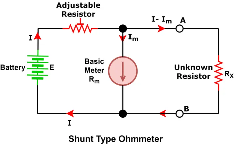
Working of Shunt Ohmmeter
When the test terminals A and B are shorted, the resistance between them becomes zero. As a result, the current prefers the low-resistance shunt path, and no current flows through the meter, causing the pointer to remain on the left side of the scale, which corresponds to zero resistance.

Conversely, when no resistance is connected across terminals A and B, the circuit is open and no current flows through the shunt path. In this case, the entire current passes through the meter, producing maximum pointer deflection toward the right side of the scale, which indicates infinite resistance (∞).
Key Characteristics of Shunt Ohmmeter
- Zero resistance → No current through meter
- High resistance → Maximum meter deflection
- Scale is opposite to series ohmmeter
3. Multi-Range Ohmmeter
A multi-range ohmmeter is designed to measure resistance over a wide range of values by using a range selector switch. This feature allows the user to select the appropriate measuring range, enabling accurate resistance measurement from very low to very high values. The basic circuit configuration of a multi-range ohmmeter is shown in the diagram below.
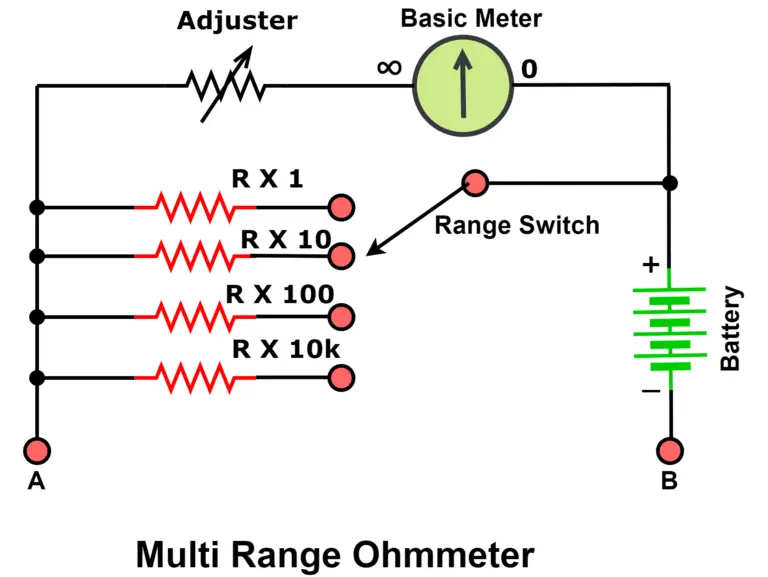
In this method, the unknown resistance is connected in parallel with the measuring instrument. The ohmmeter is first calibrated so that it produces full-scale deflection when the selected resistance range is applied using the range selector switch.
When the resistance under test is zero (short-circuited), the current bypasses the meter movement, resulting in no pointer deflection. To measure very low resistance values—such as those below 1 ohm—the appropriate low-resistance range is selected initially.
Once the resistor is connected across the terminals, the meter deflection is observed. A resistance equal to the selected range produces full-scale deflection, while higher or lower resistance values result in proportional pointer movement below full scale. This allows the resistance value to be read accurately from the calibrated scale.
Due to its high accuracy, wide usability, and precise low-resistance measurement capability, this method is considered one of the most effective ohmmeter techniques and is widely used in modern electrical testing and troubleshooting applications.
How to Measure Resistance Using an Ohmmeter (Step-by-Step)
- Power OFF the circuit completely.
- Discharge capacitors (if present).
- Set the ohmmeter to the appropriate range.
- Short the test leads and adjust the zero (analog meters).
- Connect the probes across the component.
- Read the resistance value from the scale or display.
Applications of Ohmmeter
An ohmmeter is widely used in electrical and electronic testing for measuring resistance and identifying faults. The major applications of an ohmmeter include:
- Checking circuit continuity to ensure that electrical paths and components are not open or broken
- Detecting open and short circuits, which helps in troubleshooting faulty wiring and components
- Testing electronic components and circuits to verify their proper operation
- PCB fault detection, including identification of open tracks and short circuits on printed circuit boards
- Measuring motor winding resistance and testing other electrical equipment for defects
- Testing heating elements to identify open or short-circuited conditions
- Electrical maintenance and troubleshooting in industrial, commercial, and domestic systems
Because of its accuracy and ease of use, the ohmmeter is an essential tool for fault diagnosis, preventive maintenance, and quality testing.
Advantages of Ohmmeter
An ohmmeter offers several advantages that make it a reliable and widely used instrument for resistance measurement and electrical testing:
- High accuracy in resistance measurement
- Fast measurement speed, enabling quick testing
- Easy and convenient to use, even for basic troubleshooting
- Versatile, suitable for a wide range of electrical and electronic applications
- Reliable results with consistent performance
- Low power consumption, ensuring longer battery life
- No hysteresis loss, improving measurement precision
- Not affected by stray magnetic fields, ensuring stable readings
Due to these advantages, ohmmeters are extensively used in laboratories, maintenance work, and field testing.
Ohmmeter vs Multimeter Comparison Table
| Feature | Ohmmeter | Multimeter |
| Measures resistance | Yes | Yes |
| Measures voltage & current | No | Yes |
| Dedicated accuracy | High | Moderate |
| Portability | Moderate | High |
| Modern usage | Limited | Very common |
Common Mistakes While Using an Ohmmeter
Using an ohmmeter incorrectly can lead to inaccurate readings, damage to the instrument, or even safety hazards. Here are some of the most common mistakes to avoid:
- Measuring Resistance in a Live Circuit
An ohmmeter is designed to measure resistance in a powered-off circuit. Connecting it to a live circuit can damage the meter or give erroneous readings. Always ensure the circuit is de-energized before testing. - Skipping Zero Adjustment on Analog Meters
Analog ohmmeters require a zero adjustment before measurement to ensure accuracy. Failing to calibrate the meter using the zero-adjustment knob can result in incorrect resistance readings, especially for low-resistance measurements. - Touching the Probe Tips
Direct contact with the probe tips can introduce body resistance, which affects the current flow and leads to inaccurate measurements. Always hold probes by the insulated handles and avoid contact with conductive parts. - Using the Wrong Range Setting
Selecting an inappropriate resistance range—too high or too low—can either prevent the pointer from moving or damage the meter. Always start with a higher range and adjust down as needed for precise readings. - Measuring Capacitors Without Discharging
Capacitors can retain a high voltage even after power is removed. Measuring them without proper discharge can harm the meter or cause electric shock. Always discharge capacitors fully before connecting the ohmmeter. - Ignoring Environmental Factors
Excessive temperature, humidity, or stray magnetic fields can affect measurement accuracy. Ensure the instrument is used in stable conditions for reliable results.
By avoiding these mistakes, users can ensure safe operation, accurate measurements, and longer instrument life.
Conclusion
An ohmmeter is a fundamental electrical measuring instrument used to determine the resistance of electrical circuits and components accurately. By operating on Ohm’s law, it enables technicians and engineers to evaluate circuit continuity, detect faults, and assess the condition of electrical equipment.
Understanding the working principle, circuit configuration, and different types of ohmmeters—including series, shunt, multi-range, micro-ohmmeters, and mega-ohmmeters—is essential for selecting the right instrument for a specific application.
When used correctly and with proper safety precautions, an ohmmeter provides fast, reliable, and precise measurements, making it an indispensable tool in electrical testing, maintenance, and troubleshooting. Despite the widespread use of digital multimeters today, the basic concepts and operation of ohmmeters remain crucial for students, professionals, and anyone working with electrical and electronic systems.
Read Next: