The foundation fieldbus is an all-digital, serial, two-way communication system. The foundation fieldbus is a multi-drop communication system and runs at a speed of 31.25 Kbits/s. The foundation fieldbus works as the base-level network in plant automation, and it has an open architecture that is developed and administered by FieldComm Group.
The foundation fieldbus connects intelligent field equipment such as smart transmitters, smart positioners, and controllers, and it carries multiple variables from each connected field device which can be brought into the control system. The foundation fieldbus is one of the smart communication systems which connects multiple field devices through one cable only to the system. Mostly, the foundation fieldbus technology was used in process industries. Recently it is also used in power plants. There are two types of foundation fieldbus that use different physical media and communication speeds.
Types of Foundation Fieldbus
There are two types of foundation fieldbus. They are
- Foundation fieldbus H1
- HSE Type( High-speed Ethernet)
Foundation fieldbus H1
The foundation fieldbus H1 operates at 31.25 Kbit/s. The foundation fieldbus H1 connects the field devices to the host systems. The foundation fieldbus H1 uses a single pair cable to provide the power to the field devices as well as receive data from them. The foundation fieldbus H1 is the most common implementation these days.
HSE type (High-speed Ethernet)
HSE-type foundation fieldbus operates at 100/1000 Mbit/s. HSE-type foundation fieldbus connects the input-output subsystems, and host systems, linking devices and gateways. HSE-type foundation fieldbus does not provide power over cable.
In the foundation fieldbus, the main process variable as well as other important information like diagnostics data is transmitted along a single wire pair. The microprocessor-based fieldbus devices help to reduce downtime and improve plant safety due to their self-diagnostics and communication capabilities.
Certain functions of a control system such as AI, proportional-integral-derivative (PID) controller, and AO can be performed by the field devices by the use of these standard function blocks.
By the distribution of control in the field devices, a significant decrease is observed in the amount of hardware needed. The multidrop connection is for connecting multiple field devices with a single cable, which means that there can be many devices connected on a single wire. Due to this, the reduction of cables offers ample advantages.
Also, when the cable is laid previously, the additional field devices can be connected later. Earlier, the multidrop connection was costly. But, the foundation fieldbus uses only a single pair of cables from the field spur junction box up to the marshaling cabinet which connects multiple field devices and ultimately reduces cost.
Analog transmission protocols compared with foundation fieldbus
The analog transmission system has only one field device which can be connected to the system using a single-pair cable. The Fieldbus differs from the analog transmission system (4-20 mA) devices in a way that the analog devices use dedicated pair of wires for each device to connect with a DCS system.
Some complex functions can also be achieved by the FF devices. By this, a significant cost saving and reduced cost of commissioning and start-up time is achieved. The FF can connect to control valves, motor-operated valves, transmitters, and local indicators. In an analog system, only 1 control valve can be controlled by a pair of a cable. But in the FF system, multiple control valves can be controlled by a single pair of cables (single pair up to field JB)
Specifications of the Standard Fieldbus
The physical fieldbus has two types, low-speed fieldbus, and high-speed fieldbus. They are standardized under the IEC61158-2 and ISA S50.02 standards. High-speed Ethernet (HSE) was then added as an additional type.
Low-speed Fieldbus (FF-H1)
Low-speed fieldbus has a transmission speed of 31.25kbps. A maximum of 32 devices can be connected per segment. The cable which should be used is a twisted pair cable (shielded) or an optical fiber cable.
High-speed Fieldbus (FF-HSE)
- High-speed fieldbus has a transmission speed of 100 Mbps.
- High-speed fieldbus depends on the subsystem integrated by FF-HSE.
- The cable which should be used is a twisted pair cable (shielded) or an optical fiber cable.
Advantages of Foundation Fieldbus
- Reduction in the number of wires
- Decrease in size of the equipment rooms
- It also has a remote and diagnostic configuration of devices.
- Provides more information for operation and maintenance.
- It also provides improved accuracy of measurements.
- Increased uptime and reduced commissioning time.
- It gives better self-diagnostics and remote diagnostics.
Disadvantages of Foundation Fieldbus
- The foundation fieldbus is not applicable for systems that need extremely fast control system response, that is, 200ms or below.
- In a single field barrier, more than one field device is connected. Hence, if the field barrier fails, or if the cable connecting the barrier to the marshaling cabinet fails, then more than one device which is connected to that particular barrier will go at fault.
Foundation Fieldbus Topologies
The foundation fieldbus follows tree topology.
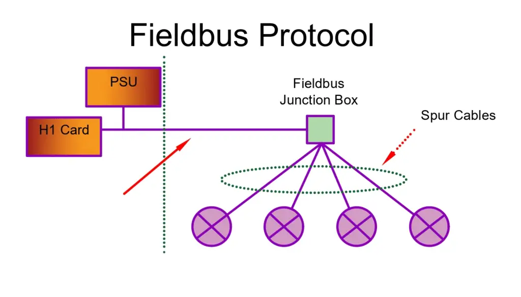
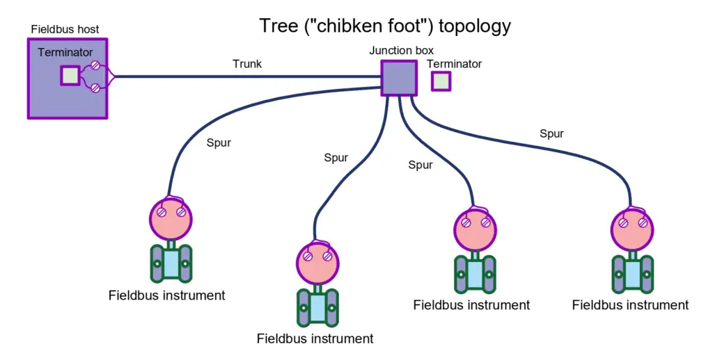
The foundation fieldbus uses chicken foot topology. In the foundation fieldbus, the power supplies are located in the marshaling cabinet which has a base plate also. This base plate is generally connected to the controllers using pre-fabricated cables.
A 5-pair cable runs from the marshaling cabinet to the intermediate junction box in the field. Now out of these 5 pairs, one pair is generally kept as a spare, and the other 4 pairs connect to 4 different spur junction boxes in the field having field barriers. These barriers have field devices connected to them using single cables.
Cables Used in FF
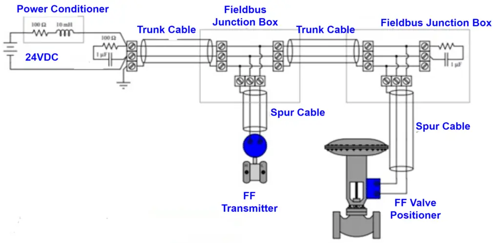
- The H1 spur cables must be single twisted pair with an overall shield. They must be compatible according to the FF-844 standard. They should come under type-A under IEC-61158-2 specifications.
- The H1 trunk cables must be multiple twisted pairs and should have individual and overall shields. They also follow standards in IEC-61158-2.
- The maximum length of FF cables including the trunk and all spurs is 1900 meters.
- The maximum trunk length in FF cables is 1200 meters.
- The maximum spur cable length based on the barrier design is 120 meters.
Specifications of Foundation Fieldbus Cables
For Foundation Fieldbus Protocol, a certain signal level is used for data transfers. For the same reason, the cable specification is very important. A total of 4 types of Fieldbus cables can be used. They are Type A, Type B, Type C, and Type D Fieldbus cables. As per Foundation Fieldbus standard, Type A cable is the most suitable and is the most widely Foundation Fieldbus cable.
Let us see all 4 types of Fieldbus cable specifications in detail.
a. Type A Fieldbus cable
Fieldbus Type A cable uses an 18 AWG (American Wire Gauge) twisted pair cable. A twisted-pair cable is used to cancel out the effect of the noise on the signal. A shield over the twisted pair is used to further reduce the effect of the noise. Fieldbus Type A cable has a wire size of 18 AWG or 0.8 mm, shield coverage of 90%, attenuation of 3 dB/km at 39 kHz, characteristic impedance of 100 Ohms +/-20% at 31.25 kHz, and allowing a maximum cable length of 1,900 m.
b. Type B Fieldbus cable
Fieldbus Type B cable is multiple-shielded pair of 22 AWG cables. The Fieldbus Type B cable type offers a characteristic impedance of 100 Ω at 31.25 kbps. One of the drawbacks of the Fieldbus Type B cable is its higher electrical resistance because of the smaller wire size. The maximum network length which can be created using Type B cable is 1,200 meters.
c. Type C Fieldbus cable
Fieldbus Type C cable is a multiple unshielded pair of 26 AWG cables. The maximum length of Fieldbus Type C cable is only up to 400 meters. The Fieldbus Type C cable is not preferred for Fieldbus cable because it does not have a shield.
d. Type D Fieldbus cable
Fieldbus Type D cable is a multicore cable that is unshielded and untwisted 16 AWG cable. The maximum length of Fieldbus Type D cable is only up to 200 meters. The Fieldbus Type D cable is also not preferred for Fieldbus cable because it does not have a shield.
Signal Strength in Foundation Fieldbus Protocol
The standard signal strength of a Foundation Fieldbus Protocol is predefined. The signal strength should be within the specified limits. The signal strength in the network can drop due to noise, excessive terminators in the loop, or any other faults in the cable or the circuit of any device.
The signal strength can increase also, which is not acceptable in the Foundation Fieldbus Protocol. This increase in the signal strength can be due to less number of terminators used in the loop or a faulty terminator used in the loop. Allowable signal strength in the Foundation Fieldbus protocol is as shown below.
| Signal level in millivolt (peak-peak) | Interpretation from the signal level |
| 800 mV or more | A missing terminator resistor or a faulty terminator |
| 350 mV to 700 mV | Excellent signal strength |
| 150 mV to 350 mV | Marginally low signal level due to extra terminator |
| 150 mV or less | Too little signal for the functioning |
Always keep 2 terminators in the loop on both ends to have excellent signal strength. We will now have a discussion on the noise levels which can affect our signal in the Foundation Fieldbus Protocol.
Noise level in Foundation Fieldbus Protocol
As the Foundation Fieldbus Protocol works on millivolt signal levels, the level of the noise in the signal plays a very important role. Below a certain level, the noise will not affect the Foundation Fieldbus signal. But above a certain level, the Foundation Fieldbus signal will start deteriorating due to the effect of the noise. Hence, it is very important to always keep the noise level below the limits specified. The noise level is measured in millivolts (peak to peak). The limits of the noise are as shown below:
| Noise level in mV (pk-pk) | Signal Interpretation |
| 25 mV or less | Excellent Signal |
| 25 mV to 50 mV | Okay Signal |
| 50 mV to 100 mV | Marginal Signal |
| 100 mV or more | Poor Signal |
This is the reason why we measure the noise level when we are facing any issue in the Foundation Fieldbus signal or any device in the network. A proper shield in the cables used for the Foundation Fieldbus protocol plays a very important role to eliminate noise and hence, Fieldbus Type-A cable is widely used.
Jitter in Foundation Fieldbus Protocol
Jitter measurement is the most accurate method used for indication of a developing fault in a foundation fieldbus device. Various organizations like MTL, P&F, Relcom, Chevron, Emerson, and Yokogawa also agreed to the fact that the jitter measurement is a very much beneficial parameter to analyze any network impedance and power supply performance in the foundation Fieldbus.
Jitter measurement is also the only parameter that allows us to measure and confirm the fieldbus power supply’s compliance with the standard IEC61158-2 and its compatibility with other devices used. Fieldbus power supply test specification FF-831 can also be verified by measuring the Jitter levels. It is very important to note that the Jitter measurement will totally ignore the effects of noise, attenuation, and distortion.
For example, say that the noise level is well within the acceptable limits. The signal attenuation and the signal distortion are also well within limits. Hence, they will not give any alarm. But collectively, they all may cause the data detection to fail. Here Jitter will help to detect the onset of the failure before any other parameter will give an indication.