Transistor Transistor logic (TTL logic) has transistors as a basic building element. Many TTL logic gates made up of transistors are fabricated on a single integrated circuit( IC) or chip.
BJT has two p-n junctions that are capable of amplifying the input signal. A BJT is a current-controlled device. The BJTs are three-terminal devices. These terminals are called emitter, base, and collector.
The low amplitude input signal is applied at the base, and its amplified form is available at the collector terminal. For the amplification process, a BJT does not need any DC power source. There are two types of BJTs, and they are- NPN and PNP-type bipolar junction transistors. The N and P are doped semiconductor materials.
Introduction to transistor-transistor logic (TTL Logic)
There are many logic families like RTL (Resistor-transistor logic), DTL (Diode-Transistor Logic), TTL (Transistor-Transistor Logic), ECL (Emitter-Coupled Logic), and CMOS (Complementary Metal Oxide Semiconductor Logic).
The transistor-transistor logic is built with the help of bipolar junction transistors (BJTs). Here two transistors are used. The first transistor performs the logic function and the second transistor performs the amplification function. The ICs made using TTL are widely used in computers, industrial controls, electronics, etc.
Transistor-Transistor Logic History
- James L. Buie of TRW invented Transistor-Transistor Logic in the year 1961. With this invented TTL, it is possible to develop new integrated circuits.
- The TTL is also called TCTL -Transistor-coupled transistor logic.
- In 1963, Sylvania manufactured TTL devices on a commercial scale. The device is also known as SUHL or the ‘Sylvania Universal High-Level Logic family’.
- In the year 1964, Texas instruments developed and launched the 5400 series TTL ICs for military applications that need a wide range of operating temperatures of ICs. Afterward, Transistor-Transistor Logic (TTL) became very popular.
- In 1966, the 7400 series was launched through a narrower temperature range.
- The compatible parts of the 7400 series families of Texas were then designed and manufactured by the companies like National Semiconductor, AMD, Motorola, Intel, Fairchild, Signetics, Intersil, Mullard, SGS-Thomson, Siemens, Rifa, etc.
- IBM designed and manufactured the 7400 series which is not compatible with others companies’ devices. They use it for their own use.
- The Transistor-Transistor Logic was further improved by improving the speed and power consumption of the devices. Each TTL integrates circuit uses hundreds of transistors and works as a single package ranging from logic gates to a microprocessor.
- The first PC like Kenbak-1 used Transistor-Transistor Logic for its central processing unit. The Datapoint 2200 used TTL components in the year 1970, and it was the base for the 8008 & after that the x86 instruction set.
- Xerox alto introduced The GU in the year 1973. In the year 1982, they used TTL integrated circuits.
What is Transistor-Transistor Logic (TTL)?
The TTL family is mainly built by NPN transistors, PN junction diodes, and some diffused resistors. For this logic family, the basic building block is the NAND gate. The examples of logic gates are 7400 (NAND gate) & 7402(NOR Gate).
Transistor-Transistor Logic (TTL) basically uses bipolar junction transistor as its basic building block. The emitters of all the transistors used in TTL have many inputs. Standard TTL, Fast TTL, Schottky TTL, High power TTL, Low power TTL & Advanced Schottky TTL are the types of TTL.
There are different types of TTL developed to achieve the achieve least power consumption & the fastest switching speed. The low-power Schottky diode. TTL has a lower power consumption and higher switching speed.
Types of Transistor-Transistor Logic
The different types of TTL are as follows.
- Standard TTL
- Schottky TTL
- Advanced Schottky TTL
- Low power TTL
- High power TTL
- Fast TTL
1. Standard TTL
This was the first to be developed among all other subfamilies of TTL. It was developed in the year 1965 and was designed to perform basic logical functions. The standard TTL is often used as glue logic devices that can connect to more complex devices in digital systems.
2. Schottky TTL
The Schottky TTL is used to speed up the execution. The speed provided by the Schottky TTL is twice that of the high-power TTL. The circuit design of high-power and Schottky TTL is almost similar. Both have the same power dissipation. The Schottky TTL has a bipolar transistor whose base and collector are connected by a Schottky diode. The Schottky TTL has other subtypes like Low Power Schottky, Extended Schottky, etc.
3. Advanced Schottky TTL
It is used to speed up the transition from low to high.
4. Low Power TTL
The low-power TTL has lower power consumption and dissipation. Their speed of operation is reduced. These are the most general type of transistor-transistor logic. They are used in glue logic in the microprocessors. The Schottky diodes help in achieving lower power consumption and high speed.
5. High Power TTL
They are the high-speed edition of the standard TTL. They have a higher speed of operation. The power dissipation is also higher in high-power TTL. They are used for increasing the transition from low to high.
The TTL design is available in a wide temperature range. For example, the 5400 series has a temperature range from −55 to +125 °C, and the 7400 series has a temperature range from 0 – 70 °.
Characteristics of TTL
The followings are the characteristics of TTL.
- Fan Out: Fan-out is a measurement of the capacity of a single logic gate that it can fan to other logic gates without affecting circuit performance. Suppose a TTL logic gate supplies its output to 10 logic gates without affecting its usual performance. It means the fan out of a logic gate is 10.
- Power Dissipation: Every electrical or electronic device consumes power for its operation. Thus, power consumption is the amount of power required by a device for its operation. The power consumption of TTL devices is given in mW(milliwatts). The power is the product of the voltage and the current drawn by the device when its output is high or low.
- Propagation Delay: The time taken to change the TTL state from high to low or low to high is called propagation delay.
- Noise Margin: The noise margin is expressed in volts. The noise margin shows the noise immunity of a circuit. The TTL device has two values of noise margin- the HIGH-level noise margin (VNH) and the LOW-level noise margin (VNL).
Classification of Transistor-Transistor Logic
Based on the output the TTL are classified as:
- Open Collector output
- Totem Pole Output
- Three State Gate
1. Open Collector Output
The most important feature of the open collector output is that it has a 0 output when the input is high and a floating output when the input is low. It generally needs an external VCC supply.
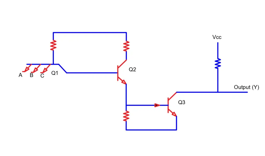
As shown in the figure above, there is a transistor Q1, which behaves like a cluster of diodes that are placed back to back. When any of the inputs is low, the respective emitter-base junction will be forward-biased. The voltage drop across the base of transistor Q1 would be around 0.9V. This is however not sufficient for the transistors Q2 and Q3 to conduct. So the output that is received is floating or equal to VCC, which means, the output is high.
When all the inputs are high, then all the base-emitter junctions of transistor Q1 are reverse bias. This will result in providing sufficient base current to the transistor Q2 and Q3. Therefore, enough base current that these transistors get ultimately drive them to saturation. The output will become low.
Applications
- Open collector transistors are used in driving lamps or relays.
- They are also used in performing weird logic.
- They are used in the construction of a common bus system.
2. Totem Pole Output
The term totem pole means the addition of an active pull-up circuit in the output side of the gate. This will result in the reduction of propagation delay
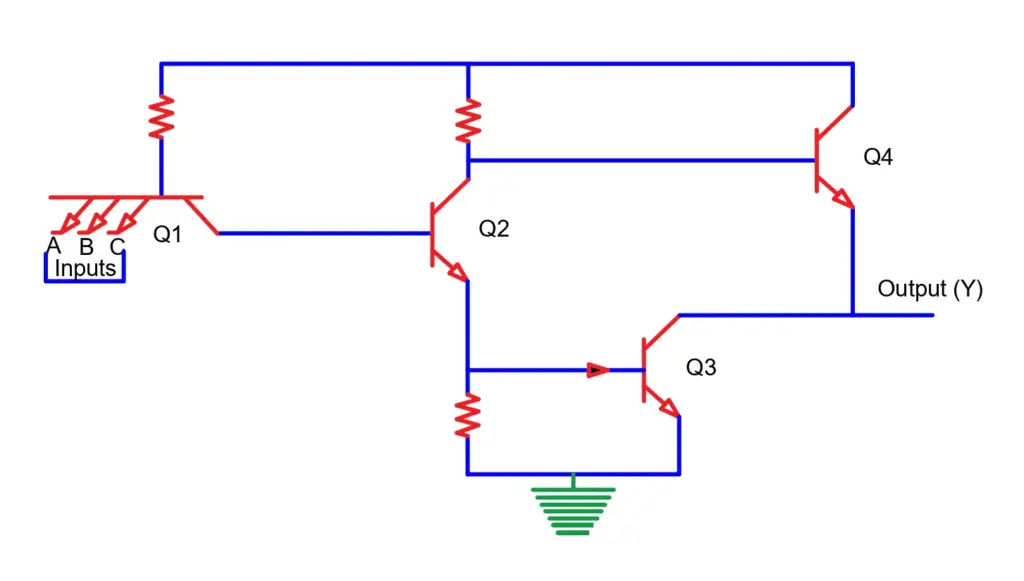
The logic operation in the totem pole output is the same as in the open collector output type. Here, the transistor Q4 and diode are used for quick charging and discharging of parasitic capacitance across Q3. The resistor keeps the output current within a safe value.
3. Three State Gate
A three-state gate as the name suggests provides a three-state output as under:
- Low-level state- It is a state when the lower transistor is ON and an upper transistor is OFF.
- High-level state- It is a state when the lower transistor is OFF and an upper transistor is ON.
- Third state- This is the state when both the transistors are OFF. This allows a direct wire connection of many outputs.
Advantages of TTL
The advantages of TTL are:
- They have low power dissipation as compared to RTL and DTL.
- They have low cost.
- They have a good fan out and noise margin.
- These are easy to interface with several circuits.
- These can generate complex logic functions.
- They are able to tolerate static electric discharges and avoid circuit damage.
- They have high reliability.
- They are faster.
Disadvantages of TTL
The disadvantages of TTL are:
- They are not suitable for high-end electronic devices and processors that have high performance.
- Their current consumption is high.
- For high-current TTLs, the switching of output states can give improper functioning.
- They cannot be used in complex logic circuits.